
Units: ft=foot, gal=US gallon, m=meter, min=minute, s=second.
Cipoletti Weir Diagrams:
Introduction
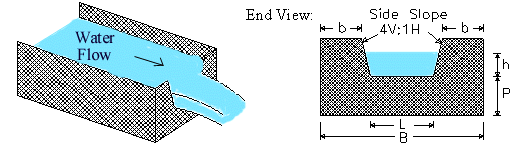
Weirs are typically installed in open channels such as streams to determine discharge
(flowrate). The basic principle is that discharge is directly related to the water
depth (h) in the figure above; h is known as the "head." The Cipoletti (or
trapezoidal) weir has side slopes in the vertical to horizontal ratio of 4 to
1. Cipoletti weirs are considered fully contracted and have the installation
requirements shown below. The discharge coefficient for Cipoletti weirs is 3.367 (in
English units), and it does not depend on L or P like it does for a rectangular weir.
Though the discharge coefficient formulation is simpler than for rectangular weirs, its
accuracy is not as good - about ±5% (USBR, 1997). Cipoletti is sometimes spelled
Cipoleti, Cipolleti, Cipolletti, Cippoleti, Cippolleti, Cippoletti, and Cippolletti.
Cipoletti Weir Equation
The Cipoletti weir equation is shown below for Q in cfs (ft3/s) and head and
length in feet units (USBR, 1997). Our calculation allows you to work in a variety
of units.
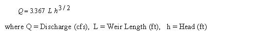
Note that L is measured along the bottom of the weir (called the crest), not along the
water surface.
Cipoletti Weir Installation Guidelines and Equation Applicability (USBR, 1997)
Cipoletti weir side slopes should have a vertical to horizontal ratio of 4 to 1.
Head (h) should be measured at a distance of at least 4h upstream of the weir.
It doesn't matter how thick the weir is except where water flows through the weir. The weir should be between 0.03 and 0.08 inches (0.8 to 2 mm) thick in the opening. If the bulk of the weir is thicker than 0.08 inch, the downstream edge of the opening can be chamfered at an angle greater than 45o (60o is recommended) to achieve the desired thickness of the edges. You want to avoid having water cling to the downstream face of the weir.
Water surface downstream of the Cipoletti weir should be at least 0.2 ft. (6 cm) below the weir crest (i.e. below the bottom of the opening).
Measured head (h) should be greater than 0.2 ft. (6 cm) but less than L/3.
P is measured from the bottom of the upstream channel and should be greater than 2hmax where hmax is the maximum expected head.
b is measured from the sides of the channel and also should be greater than 2hmax.
Error Messages
"All inputs must be positive". This is an initial check
of user input.
Reference
USBR (1997). U.S. Department of the Interior, Bureau of Reclamation. Water Measurement
Manual. 1997. 3ed. Available from http://www.usbr.gov/tsc/techreferences/mands/wmm/index.htm
.
© 1999-2026 LMNO Engineering, Research, and Software, Ltd. All rights reserved.
LMNO Engineering, Research, and Software, Ltd.
7860 Angel Ridge Rd. Athens, Ohio 45701 USA Phone: (740) 707-2614
LMNO@LMNOeng.com
https://www.LMNOeng.com