
Units: barrel=42 U.S. gallons, cm=centimeter, cP=centiPoise, cSt=centiStoke, ft=foot, g=gram, gal=U.S. gallon, hr=hour, kg=kilogram, kPa=kiloPascal, lb=pound, m=meter, min=minute, mm=millimeter, N=Newton, psf=pound per square foot, psi=pound per square inch, s=second, SSU=Saybolt universal seconds.
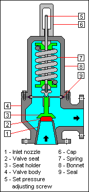
Pressure Relief Valve Drawing (Spring) (with permission of Wikimedia Commons).
Introduction
Pressure relief valves are installed in nearly all refinery, chemical, and industrial facilities. Pressure relief valves are installed to protect equipment from failing due to over-pressurization. The calculation on this page is specifically for sizing and flow rate determination for rupture disks, spring pressure relief valves, and pilot operated pressure relief valves, or valves that have a rupture disk in combination with a spring or pilot operated relief valve for the flow of liquids. Balanced bellows valves can be spring or pilot operated and are specified where backpressure is expected.
The equation methodology on this web page mostly follows the American Petroleum Institute standard 520 for pressure relief valve sizing for liquids in order to protect equipment having a maximum allowable working pressure of 15 psig (103 kPa gage) or greater (API, 2014, p. 1). For an orifice in a pipe (rather than in a relief valve), LMNO Engineering has written additional software based on ISO (International Organization for Standardization) methodologies. The calculations can be seen by clicking on the links in the yellow background on the right side of this page.
LMNO Engineering's pressure relief valve for liquids calculator can compute relief valve area or flow rate. If area is computed, the area will be shown for the inputs that you enter. After viewing the area, refer to a pressure relief valve manufacturer's catalog and select a relief valve having the area computed or, if such a pressure relief valve is not available, the next larger area. Then, re-run our calculator using the manufacturer's actual area to compute the liquid flow rate through the pressure relief valve.
Equations
The following methodology is used to compute relief valve area or flow rate.
Discharge coefficient, Kd
The following guidance is from API (2014, p. 76):
If there is a pressure relief valve with or without a rupture disk, enter Kd of 0.65.
If there is only a rupture disk, enter Kd of 0.62.
If there is a value provided by the valve manufacturer, enter the manufacturer's value for Kd.
Combination correction factor, Kc
Guidance from API (2014, p. 76):
If there is no rupture disk with the pressure relief valve, enter Kc=1.0.
If there is only a rupture disk (no relief valve), enter Kc=1.0.
If there is a rupture disk and a pressure relief valve, enter Kc=0.9.
If there is a value provided by the valve manufacturer, enter the manufacturer's value for Kc.
Upstream relieving pressure, P1
The upstream relieving pressure (expressed as a gage pressure) is computed from the set pressure (expressed as a gage pressure) and overpressure percent (API, 2014, p. 76; Crowl & Tipler, 2013, p. 73):
P1 = Ps (1+ 0.01Po)
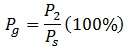
Percent gage back pressure, Pg
The percent gage back pressure is computed from the back pressure (expressed as gage) and set pressure (expressed as gage) (API, 2014, p. 49 Figure 31; Crowl & Louvar, 2011, Figure 10-4):
Back pressure correction factor, Kw
Kw is set automatically by the LMNO Engineering calculation based on your selection of "Spring and pilot operated valves" or "Balanced bellows valve." The following guidance is from API (2014, p. 76, Figure 31):
For spring and pilot operated relief valves, Kw=1.0 (set by LMNO Engineering calculation by selecting "Spring and pilot operated valves").
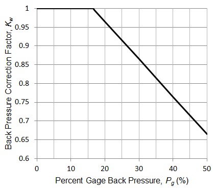
For balanced bellows relief valves, a graph for Kw is provided in API (2014, p. 49, Figure 31). Crowl & Louvar (2011, Figure 10-4) provide an equation fit to the API graph. The equation is:
Kw = 1.165 - 0.01Pg
The equation is valid in the range 16.5% ≤ Pg ≤ 50%. Thus, in LMNO Engineering's calculation above when a balanced bellows valve is selected, Kw is:
If Pg < 16.5%, Kw=1.0.
If 16.5% ≤ Pg ≤ 50%, the Kw equation is used.
If Pg > 50%, Kw is not defined.
Graphically, the equation for Kw for a balanced bellows pressure relief valve is:
Viscosity correction factor, Kv
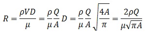
Kv is a function of Reynolds number. Reynolds number in general is defined in terms of mass density, velocity, diameter, and dynamic viscosity (Munson et al., 1998, p. 462):

Velocity in terms of flow rate and effective discharge area, as well as area in terms of diameter:
![]()
In the pressure relief valve literature, Reynolds number is often written in terms of area. Thus, making the above substitutions:
API (2014, p. 76) provides an equation for Kv for 0.3 ≤ Kv ≤ 1:
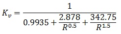
A graphical representation of Kv developed from the equation is:
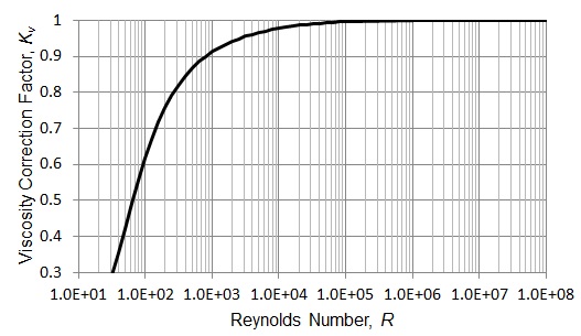
Thus for Kv in LMNO Engineering's pressure relief valve calculator:
If R < 32.662, Kv is not defined.
If 32.662 ≤ R ≤ 192,282.5, the equation above for Kv is used.
If R > 192,282.5, Kv=1.
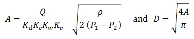
Computation of pressure relief valve area and diameter
Equations for area and diameter of the pressure relief valve written in general with K-factors (similar to Crowl & Tipler, 2013, p. 73; Crowl & Louvar, 2011, Eqn 10-2; API, 2014, p. 76):
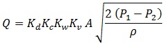
Pressure relief valve flow rate equation:
Since either area or flow rate is to be computed, Reynolds number is not known directly. Thus, an iterative solution is used which converges when the percent change in area or flow rate (whichever is being computed) is less than 10-10.
Variables
Units shown in SI for use in equations: kg=kilogram, m=meter, N=Newton, s=second (the calculator allows a variety of units).
A = Effective discharge area, m2.
D = Diameter, m.
g = Acceleration due to gravity = 9.8066 m/s2.
Kc = Combination correction factor.
Kd = Effective discharge coefficient.
Kv = Viscosity correction factor.
Kw = Back pressure correction factor.
Pg = Percent gage backpressure, %.
Po = Percent overpressure (gage), %.
Ps = Set pressure, N/m2 gage.
P1 = Upstream relieving pressure, N/m2 gage.
P2 = Total backpressure, N/m2 gage.
Q = Liquid flow rate, m3/s.
R = Reynolds number.
V = Velocity, m/s.
π = 3.1415926...
μ = Dynamic viscosity, kg/m-s (i.e. N-s/m2).
ρ = Mass density, kg/m3.
LMNO Engineering uses the viscosity unit conversion from SSU to m2/s of 1 SSU = 2.2e-7 m2/s. However, if viscosity in SSU is less than 100 SSU, the relation between SSU and m2/s is significantly non-linear. Therefore, the unit conversion is not valid, and a different viscosity unit should be selected. Additional discussion of SSU can be found in Weast (1984, p. F-36).
Error Messages
Initial checks:
"Need A > 0",
"Need D > 0",
"Need Ps > 0",
"Need P2 ≥ 0",
"Need 1e-30 ≤ Q ≤ 1e30 m3/s",
"Need 0 ≤ Po ≤ 100",
"Need 1e-9 ≤ Density ≤ 1e9 kg/m3",
"Need 1e-19 ≤ Viscosity ≤ 1e9 m2/s",
"Need 0 < Kc ≤ 1",
"Need 0 < Kd ≤ 1".
Run-time messages:
"Invalid input: P1 will be ≤ P2",
"Pg out of range",
"R out of range: Q too small",
"R out of range: A too small",
"Solution not found".
References
American Petroleum Institute. (2014, July). Sizing, selection, and installation of pressure-relieving devices in refineries. Part I - Sizing and selection. API Recommended Practice 520. 9ed.
Crowl, D. A. & Louvar, J. F. (2011). Chemical process safety: Fundamentals with applications. 3ed. Prentice Hall.
Crowl, D. A. & Tipler, S. A. (2013, Oct.). Sizing pressure-relief devices. CEP. American Institute of Chemical Engineers. Retrieved from
https://www.aiche.org/sites/default/files/cep/20131068_r.pdf
Munson, B. R., Young, D. F. & Okiishi, T. H. (1998). Fundamentals of fluid mechanics. 3ed. John Wiley & Sons, Inc.
Pentair Valves and Controls. (2012). Pentair pressure relief valve engineering handbook. Retrieved from
https://www.iomosaic.com/diersweb/docs/pvcmc-0296-us_tcm106-35825.pdf
Weast, R. C. (Ed.) (1984). Handbook of chemistry and physics (65ed.). Chemical Rubber Company (CRC), Inc.
Wikimedia Commons. Author: Milton Beychok (Mbeychok). Retrieved from https://commons.wikimedia.org/wiki/File:Relief_Valve.png
© 2018-2026 LMNO Engineering, Research, and Software, Ltd. All rights reserved.
LMNO Engineering, Research, and Software, Ltd.
7860 Angel Ridge Rd. Athens, Ohio 45701 USA Phone: (740) 707‑2614
LMNO@LMNOeng.com
https://www.LMNOeng.com