
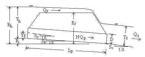
Diagram of Flow through a Culvert
Topics: Introduction Equations Variables Values of Coefficients and Manning n Error Messages and Validity References
In the Culvert Design Calculator Above:
• Culvert Types:
"Conc. Sq edge. Wall" = Concrete pipe with square edged inlet
and headwall
"Conc. Groove. Wall" = Concrete pipe with groove end at inlet
and headwall
"Conc. Groove. Proj" = Concrete pipe with groove end
projecting at inlet
"CMP. Headwall" = Corrugated metal pipe with headwall at
inlet
"CMP. Mitered" = Corrugated metal pipe mitered to slope at
inlet
"CMP. Projecting" = Corrugated metal pipe projecting at inlet
• Units:
m=meters, ft=feet, l/s=liter/sec, cfm=cubic feet per minute, cfs=cubic feet per second,
gpm=US gallons per minute, gph=US gallons per hour, gpd=US gallons per day, MGD=Millions
of US gallons per day.
• You can enter tailwater depth (Yt) as a negative number if flow from the culvert drops down to a receiving channel. You don't need to know the exact elevation drop; entering any negative number for Yt will have the same effect.
• The phrase "Inlet Control" or "Outlet Control" that appears in the upper right hand corner of the calculation refers to the type of control for the total flow (Qt) entered in the calculation's upper left hand corner. The graph below the calculation plots headwater depth (Yh) for the range of minimum Qt to maximum Qt entered under the word "GRAPHING:" in the calculation. The type of control may change from one part of the graph to another as Qt changes.
Introduction
Back to Calculation
Culverts have been utilized for thousands of years as a means to transmit water under walkways or roads. Often, a culvert is simply installed without much thought to how much water it needs to convey under extreme conditions. If a culvert cannot convey all of the incoming water, then the water will flow over or around the pipe, or simply back up behind the culvert creating a pond or reservoir. If any of these conditions are unacceptable, then the proper culvert diameter and number of culverts must be selected prior to installation in order to convey all of the anticipated water through the pipe(s). This calculation helps the designer size culverts as well as present a headwater depth vs. discharge rating curve.
Culvert design calculator is primarily based on the methodology presented in Hydraulic Design of Highway Culverts by Normann (1985) and published by the U.S. Department of Transportation's Federal Highway Administration. It is also known as HDS-5 (Hydraulic Design Series No. 5). HDS-5 focuses on culvert design. Culvert design is usually based on the maximum acceptable discharge - thus the HDS-5 methodology is geared toward culverts flowing full with water possibly flowing over the road above the culvert. In addition to programming the HDS-5 methodology, LMNO Engineering wished to compute headwater depths for lesser flows. Therefore, in addition to the HDS-5 methodology, we have added the Manning equation for culverts flowing partially full. The HDS-5 methodology also assumes that the user knows the tailwater depth (Yt) before using the methodology. Though Yt can be found by field measurements, it is often computed in the office using Manning's equation based on bottom width, side slopes, channel roughness, and channel slope. Therefore, LMNO Engineering added the additional feature of a built-in subroutine for computing Yt for trapezoidal channels. Note that for the graphing portion of our calculation, Yt is re-computed for the entire range of flows (Qt) shown on the graph (unless the user specifically inputs Yt).
As explained in Normann, 1985 (also known as HDS-5, Hydraulic Design of Highway Culverts), the discharge through a culvert is controlled by either inlet or outlet conditions. Inlet control means that flow through the culvert is limited by culvert entrance characteristics. Outlet control means that flow through the culvert is limited by friction between the flowing water and the culvert barrel. The term "outlet control" is a bit of a misnomer because friction along the entire length of the culvert is as important as the actual outlet condition (the tailwater depth). Inlet control most often occurs for short, smooth, or greatly downward sloping culverts. Outlet control governs for long, rough, or slightly sloping culverts. The type of control also depends on the flowrate. For a given culvert installation, inlet control may govern for a certain range of flows while outlet control may govern for other flowrates. If the flowrate is large enough, water could go over the road (or dam). In this case, the calculation automatically computes the amount of water going over the road and through each culvert, as well as the headwater depth.
If you have surfed around our website, you may have noticed our other calculations for
circular culverts. We have a calculation using Manning's
equation for design of circular culverts. Since it uses Manning's equation, it
assumes the culvert is long enough so that normal depth is achieved. We also have a
calculation for computing discharge from the
exit depth ("end depth") in a circular culvert - very useful for flow rate
measurement in the field. For flows under pressure, we have several calculations
listed under the Pipe Flow category on our home page.
Equations and Methodology
Back to Calculation
The LMNO Engineering methodology for the culvert design calculator generally follows that of Normann (1985; also known as HDS-5 - Hydraulic Design of Highway Culverts). However, the Normann methodology is mainly for culvert design. Culvert design usually involves the largest expected flowrate. We wanted to write a calculation that also determines headwater depth for small flowrates. Therefore, in addition to the Normann methodology, we have incorporated Manning's equation for outlet control when the headwater depth is less than 0.93 times the culvert diameter. 0.93D is used since it is the depth at which discharge through a partially full circular culvert is a maximum (Chow, 1959). At depths greater than 0.93D and for full flow, the Nomann (1985) equation is used for outlet control. For inlet control, our calculation uses Normann's equations.
Many of the equations shown below for the culvert design calculator are empirical and require U.S. Customary units (feet, seconds, and radians). Some of the equations are based on first principles and are compatible with any consistent set of units (e.g. SI). However, to keep this web page from being "too busy", we have refrained from indicating which equations are empirical and which are fundamental. If you work through the equations by hand, please use feet, seconds, and radians in all of them, to avoid any problem with units. Our calculation (above) allows many different types of units; the units are internally converted before and after using the equations.
Since total flow rate (Qt) is entered and headwater depth (Yh) is computed, the equations below are solved simultaneously to determine Yh. Outlet versus inlet control is determined by the equation resulting in a larger value for Yh.
All of the variables are defined below in the Variables section. Pipe downstream invert elevation is defined as 0.0.
General Equations
Qt = Qr + N Qp Sp = Sc
- Yf /Lp Ei = Lp Sp
Eh = Ei + Yh
V=Qp /Av
Tailwater Depth, Yt
Yt can be computed or input. If it is computed, Manning's
equation is used (Chow, 1959):

Since Qt is input, the above equations are solved numerically (backwards) for Yt.
Headwater depth, Yh
Yh is computed independently based on inlet and outlet control
equations. The equation that gives the larger value of Yh is
considered to be the controlling mechanism and is reported.
Inlet Control (see below
for values of constants C1, C2, C3, C4 , C5)
Outlet velocity (V) is computed based on what we call the velocity depth, Yv.
Normann (1985) suggests computing Yv using the Manning equation.
If Yv is greater than D, then Yv is set
to D.
Unsubmerged Inlet (Normann, 1985):
Submerged Inlet (Normann, 1985):
Outlet Control
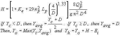
Outlet velocity (V) is computed based on what we call the velocity depth, Yv.
Normann (1985) suggests: If Yt≤Yc, then Yv=Yc.
If Yc<Yt<D, then Yv=Yt.
If Yt≥D, then Yv=D.
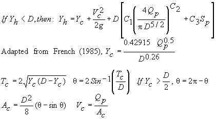
If Yh<0.93D, then Manning's equation (Chow, 1959) is used:
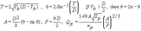
Since Qp is input, the above equations are solved numerically for Yh.
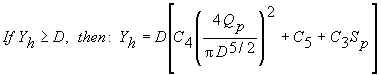
If Yh≥0.93D, Normann (1985) is used:
Flow over Road (or Dam)
If water flows over the road (or dam), then flow over the road is computed by (Normann,
1985):
![]()
Note that, instead of using a constant value of 3, Normann (1985) uses a coefficient that varies from 2.5 to 3.1 depending on the water depth above the road and whether the road is paved or gravel.
Variables
Back to Calculation
A=Flow area [ft2].
Ac=Flow area in one pipe based on critical depth [ft2].
Av=Flow area in one pipe used for computing outlet velocity [ft2].
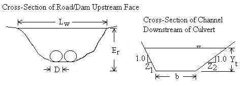
b=Width of channel bottom [ft]. Used for computing Yt.
C1, C2, C3, C4, C5=Constants
for inlet control equations. See values below.
D=Diameter of each pipe (culvert) [ft].
Eh=Headwater elevation relative to invert of pipe outlet [ft].
Pipe outlet invert elevation is defined at 0.0 ft.
Ei=Elevation of pipe inlet invert relative to pipe outlet invert [ft].
Pipe outlet invert elevation is defined at 0.0 ft.
Er=Elevation of road (or dam) crest relative to pipe outlet invert
[ft]. Pipe outlet invert elevation is defined at 0.0 ft.
g=Acceleration due to gravity, 32.174 ft/s2.
H=Head loss computed from outlet control equation [ft].
HW=Abbreviation for headwater.
Ke=Minor loss coefficient for pipe inlet (used for outlet control
equations). See values below.
Lp=Pipe (culvert) length [ft]. If there is more than one
culvert, they all must have the same length. Lp is the length of
one of them (not the sum of the lengths).
Lw="Weir" length [ft]. Length of the road (or dam)
that water could flow over. Lw is the width that the water sees
as it flows over the road.
nc=Channel Manning n coefficient. See values
below.
np=Pipe (culvert) Manning n coefficient. See
values below.
N=Number of pipes (culverts) next to each other.
P=Wetted perimeter [ft].
Qp=Flowrate (discharge) through each pipe [cfs, ft3/s].
Qr=Flow rate (discharge) over the road (or dam) [cfs].
Qt=Total flowrate (discharge) [cfs]. Sum of flows through pipes plus flow
over road.
Sc=Slope of existing channel [elevation change/length].
Longitudinal slope, not side slopes.
Sp=Pipe slope [elevation change/length]. Longitudinal slope, not
side slopes.
Tc=Top width of flow in one pipe based on critical depth [ft].
V=Pipe outlet velocity [ft/s].
Vc=Pipe velocity based on critical depth [ft/s].
Yavg=Average water depth [ft].
Yc=Critical water depth [ft].
Yf=Fall [ft]. Vertical distance that inlet pipe invert is
lowered below the existing channel bottom.
Yh=Headwater depth [ft].
Yo=Water outlet depth [ft].
Yt=Tailwater depth [ft]. Depth of water in existing channel at
culvert outlet.
Yv=Depth used for computing outlet velocity [ft].
z1=Left side slope of existing natural channel [horizontal/vertical].
z2=Right side slope of existing natural channel [horizontal/vertical].
π=Greek letter "pi" = 3.1415926...
θ=Greek letter "theta". Used for partially full pipes.
Values of Coefficients and Manning n
Back to Calculation
Manning n values are from Chow (1950), French (1985), Mays (1999), Normann (1985), and Streeter (1998). C1 through C5 and Ke are from Normann (1985).
| Pipe material and inlet type | Manning n | C1 | C2 | C3 | C4 | C5 | Ke |
| Concrete. Square edge inlet with headwall. | 0.013 | 0.0098 | 2.0 | -0.5 | 0.0398 | 0.67 | 0.5 |
| Concrete. Groove end inlet with headwall. | 0.013 | 0.0078 | 2.0 | -0.5 | 0.0292 | 0.74 | 0.2 |
| Concrete. Groove end projecting at inlet. | 0.013 | 0.0045 | 2.0 | -0.5 | 0.0317 | 0.69 | 0.2 |
| Corrugated metal (CMP). Headwall at inlet. | 0.022 | 0.0078 | 2.0 | -0.5 | 0.0379 | 0.69 | 0.5 |
| Corrugated metal (CMP). Mitered to slope at inlet. | 0.022 | 0.0210 | 1.33 | 0.7 | 0.0463 | 0.75 | 0.7 |
| Corrugated metal (CMP). Projecting at inlet. | 0.022 | 0.0340 | 1.50 | -0.5 | 0.0553 | 0.54 | 0.9 |
| Material | Manning n | Material | Manning n |
| Natural Streams | Excavated Earth Channels | ||
| Clean and Straight | 0.030 | Clean | 0.022 |
| Major Rivers | 0.035 | Gravelly | 0.025 |
| Sluggish with Deep Pools | 0.040 | Weedy | 0.030 |
| Stony, Cobbles | 0.035 | ||
| Floodplains | |||
| Pasture, Farmland | 0.035 | Heavy Brush | 0.075 |
| Light Brush | 0.050 | Trees | 0.15 |
Error Messages and Validity
Back to Calculation
Input checks on left side of calculation. If one of these
messages appears, the calculation and graphing is halted.
"Need 0≤Qt<10000 m3/s". Total flow
cannot be negative or must be less than 10,000 m3/s.
"Need 0<N<1001". Must have at least one pipe, but no more
than 1000 pipes.
"Need 0<D<100 m". Pipe diameter must be positive and less
than 100 m.
"Need 0<Lp<10000 m". Pipe length must be positive and less
than 10,000 m.
"Need 0<Pipe n<0.05". Pipe Manning n must be positive and
less than 0.05.
"Need Yt<Er". Tailwater depth cannot be
higher than the road crest.
"Need Ei+D<Er". Upstream pipe invert
plus culvert diameter cannot exceed road crest elevation. If Ei+D
is greater than Er, then the top of the culvert is pushing through the
road, which is unacceptable.
"Need 0<Lw<10000 m". "Weir" length of
road (or dam) must be positive and less than 10,000 m.
"Need Yt<10000 m". Tailwater depth must be less
than 10,000 m. Negative values are acceptable. Negatives simulate culverts
discharging to a lower channel.
"Need Sc<0.5". Channel bottom slope cannot exceed
0.5 m/m (vertical to horizontal ratio). This is the longitudinal slope, not the side
slopes.
"Need Sc>0". Channel cannot be horizontal.
"Need 0<Chan n<0.5". Channel Manning n must be positive and
less than 0.5.
"Need 0<b<10000 m". Channel bottom width must be positive
and less than 10,000 m.
"Need 0<z1<10000", "Need 0<z2<10000".
Channel side slopes can be neither exactly vertical (z=0) nor nearly flat
(z>10,000). z is defined as horizontal to vertical ratio.
"Need 1e-7<Sp<0.5". Pipe slope must be between
these limits.
Input checks for graph and chart (table). If one of these messages
appears, the graph and table will not proceed. Note that if any value is out of range in the
upper portion of the calculation, a graph will not be shown.
"Need min Qt≥0". Minimum total flow for graph was
entered as a negative number.
"Max Qt>10000 m3/s". Maximum total flow
for graph cannot exceed 10,000 m3/s.
"Min must be < Max". Minimum Qt entered
for graph must be less than maximum Qt entered for graph.
"Need Min/Max<0.99". Minimum Qt entered
for graph must be less than 0.99 times maximum Qt entered for graph.
Otherwise, the minimum and maximum are too close together to have good axis labels for the
graph.
Run-time errors. The following message may be generated
by the graphing/table portion of the calculation:
"Yt>Er for some Qt".
Tailwater depth exceeds road (or dam) crest for large values of Qt.
Yh cannot be computed or graphed when Yt>Er
since the equations are only valid for Yt≤Er.
References
Back to Calculation
Chow, V. T. 1959. Open-Channel Hydraulics. McGraw-Hill, Inc. (the classic text)
French, R. H. 1985. Open-Channel Hydraulics. McGraw-Hill Book Co.
Mays, L. W. editor. 1999. Hydraulic design handbook. McGraw-Hill Book Co.
Normann, J. M. 1985. Hydraulic design of highway culverts. HDS-5 (Hydraulic Design Series 5). FHWA-IP-85-15. NTIS publication PB86196961. Obtainable at https://www.fhwa.dot.gov/engineering/hydraulics/library_arc.cfm?pub_number=7&id=13.
Streeter, V. L., E. B. Wylie, and K. W. Bedford. 1998. Fluid Mechanics. WCB/McGraw-Hill. 9ed.
© 2001-2025 LMNO Engineering, Research, and Software, Ltd. All rights reserved.
LMNO Engineering, Research, and Software, Ltd.
7860 Angel Ridge Rd. Athens, Ohio 45701 USA Phone: (740) 707‑2614
LMNO@LMNOeng.com
https://www.LMNOeng.com