
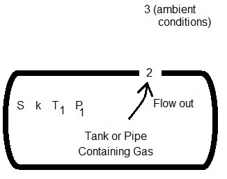
Gas Leak Diagram
Gas leaks (flows) out of the pipe (or tank) at flow rate W through the crack (or hole) at location 2.
Units: atm=atmosphere, cm=centimeter, ft=foot, g=gram, hr=hour, k=kilo (1000), kPa=kiloPascal, kg=kilogram, lb=pound, m=meter, min=minute, mm=millimeter, M=Mega (million, 106) or Thousand (103) depending on context, MM=Million, MPa=MegaPascal, Mscfh=thousand std cubic foot per hour, MMscfd=million std cubic foot per day, N=Newton (force) or Normal (standard conditions), N/m2=Newton per square meter (same as Pascal), Pa=Pascal, s=second, psf=pound per square foot (lb/ft2), psia=pound per square inch absolute, scfd=standard cubic foot per day, scfh=standard cubic foot per hour, scfm=standard cubic foot per minute.
Standard Conditions: In our gas leak rate calculation, standard conditions are 15 oC (i.e. 288.15 K, 59 oF, 518.67 oR) and 1 atm (i.e. 101,325 N/m2, 14.696 psia) (Perry, p. 3-167).
Introduction
Gas can intentionally or unintentionally be vented (leaked) from a tank or pipe to the surrounding air.
The gas venting may occur through an orifice, crack, or other opening in the pipe wall.
This discussion will use the terms pipe and tank interchangeably and will use the terms orifice, crack, and hole interchangeably.
Depending on the type of gas, temperature, and pressures, the gas flow may either be choked or subsonic as it exits through the hole.
If flow is choked, the gas exits the tank at sonic velocity (Mach number of 1).
If flow is subsonic, then the discharge Mach number is less than 1.
As gas leaks through the crack, temperature drops. If the gas contains water vapor, then there is a possibility of freezing.
In the diagram above, the gas in the pipe has specific gravity S (molecular weight Mw) and is at temperature T1 and pressure P1. The gas leaks out a hole of diameter d (or crack of area A) at flow rate W, velocity V2, Mach number M2, pressure P2, and temperature T2. Gas discharge is to ambient conditions at pressure P3. If the gas flow is subsonic, then P2=P3. If the gas flow is sonic (choked), then P2≥P3. Our gas leak rate calculator determines whether the flow of gas is choked (M2=1) or is subsonic (M2<1) and determines the gas leak rate accordingly.
Gas Leak Rate Calculator Equations
The gas flow equations from location 1 to 2 assume one-dimensional isentropic (adiabatic reversible) subsonic or sonic steady flow of an ideal gas discharging from a tank (or pipe) through a hole (or crack) to ambient conditions (Daugherty, pp. 274-276; Shapiro, pp. 83-100). However, an orifice gas discharge coefficient C is included to account for multi-dimensional effects and gas streamline contraction losses as the gas flows from the tank through the hole (Kayser, p. 1698; Shapiro, pp. 83-100). The gas flow equations assume that the velocity through the crack is much higher than the velocity in the pipe. This occurs if the hole diameter is much smaller than the pipe diameter. Adiabatic conditions occur when the gas flows out of the tank rapidly or when the tank is thermally insulated. There is no heat transfer with the environment. In addition, if friction is negligible, then the process is reversible. An adiabatic and reversible process is isentropic (Saad, p. 103). The gas discharge coefficient C helps to account for real-world behavior of the gas leak.
If orifice diameter is entered, then:
![]()
Gas specific gravity and molecular weight are related by the following equation:

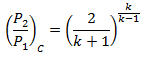
Gas critical pressure ratio (Munson, p. 719; White, p. 609; Daugherty, p. 274):
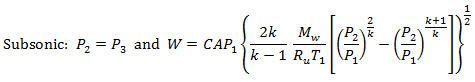
If P3/P1 > (P2/P1)c, the gas flow out of the crack is subsonic and (Daugherty, p. 275; with gas discharge coefficient C included in Kayser, p. 1698-1699):
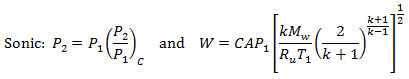
Otherwise, P3/P1 ≤ (P2/P1)c and gas flow out of the orifice is sonic (choked). Then (Daugherty, p. 275; Kayser, p. 1699):
Density of gas at standard conditions:

Gas flow rate at standard conditions:

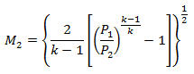
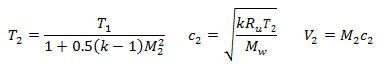
Throat Mach number, gas temperature, gas speed of sound, and gas velocity (Munson, pp. 708-718):
Gas Discharge Coefficient
The gas discharge coefficient C is neglected in some references but included in others. C must be in the range 0<C≤1. Daugherty leaves C out, which means that C is implied to have a value of 1 (a perfectly efficient nozzle shape). However, research has been conducted to determine the gas discharge coefficient's value under different conditions. Engineers Edge indicates a value of 0.72.
Kayser and Shambaugh conducted research for gas flows out of small diameter orifices and nozzles discharging to the ambient atmosphere from a tank.
Their C values were dependent on hole geometry and pressure ratio, and somewhat dependent on throat Reynolds number. The C value increased with P1/P3 ratio for subsonic flows and plateaued in the sonic range. Kayer's experiments showed that higher gas flow rates gave higher C values, indicating more efficient conditions. In general C varied from about 0.6 to 0.9. Within that range, higher C values are achieved by rounding the hole and increasing the flow rate. Shapiro (pp. 93-100) indicated that well-designed rounded entrances can have gas discharge coefficients around 0.98 and 0.99 except for flows at very low Reynolds numbers where the C value would be much lower. For sharp-edged orifices, C can be 0.6 (Shapiro, p. 100). Our gas leak rate calculation uses a default value of 0.8, which LMNO Engineering suggests is a reasonable value for many situations. The user can change this value according to the geometry of the hole and other considerations.
Variables
The units shown for the variables are SI (International System of Units); however, the
equations above are valid for any consistent set of units. Our calculation allows a
variety of units; all unit conversions are accomplished internally.
A = Hole (or crack) area, m2.
c = Speed of sound in gas, m/s.
C = Gas discharge coefficient (0<C≤1; see section above).
d = Hole diameter, m.
k = Gas specific heat ratio. Specific heat at constant pressure divided by specific heat
at constant volume, Cp/Cv. Default values at 15oC or 20oC
from Munson et al. (1998). k actually varies with gas temperature and can range from, using
methane as an example, 1.32 at 50oF to 1.28 at 250oF (GPSA, p.
13-6).
M = Mach number.
Mw = Molecular weight of gas, kg/mole.
Mw,a = Molecular weight of standard air = 0.02896443 kg/mole (CRC, p. F-164).
P = Absolute pressure, N/m2 absolute.
Qs = Flow rate at standard conditions, Normal m3/s.
Ru = Universal gas constant, 8.3144126 N-m/mole-K (CRC, p. F-208).
S = Specific gravity of gas, relative to air (Sa=1).
T = Absolute temperature of gas, Kelvin.
V = Velocity of gas, m/s.
W = Mass flow rate of gas, kg/s.
π = 3.14159....
ρ = Gas density, kg/m3.
Subscripts:
1 = Inside tank or pipe.
2 = In throat of hole or crack.
3 = Ambient (surroundings).
c = critical (i.e. choked, sonic) condition.
a = air.
s = std = Standard (or "Normal") conditions. The word "standard" is
used for English units. The term "Normal" is used with SI units.
Some industries use different temperature and pressure for standard (or Normal)
conditions. To convert the gas mass flow rate computed by our gas leak flow rate calculation to
volumetric flow at a different Ts and Ps, use our gas flow conversions page.
Error Messages
"Need S and Mw ≥ 1e-50",
"Need k ≥ 1.0000001",
"Need d ≥ 1e-50",
"Need A ≥ 1e-50",
"Need T1 ≥ 1e-50 K",
"Need P1 ≥ 1e-50 absolute",
"Need P3 ≥ 1e-50 absolute",
"Need P1 > P3"
References
Chemical Rubber Company (CRC). (1983). CRC Handbook of Chemistry and
Physics. Weast, Robert C., editor. 63rd edition. CRC Press, Inc. Boca Raton, Florida.
Daugherty, R. L., Franzini, J. B. and Finnemore, E. J. (1985). Fluid Mechanics with Engineering Applications. McGraw-Hill. 8ed.
Engineers Edge. (2020). Gas discharge rate atmosphere from a pressure vessel. Retrieved from https://www.engineersedge.com/pressure,045vessel/gas_discharge_rate_14170.htm
Gas Processors Suppliers Association (GPSA). (1998). Engineering Data Book (fps [foot-pound-second] version). Gas Processors Association. 11ed.
Kayser, J. C. and Shambaugh, R. L. (1991). Discharge coefficients for compressible flow through small-diameter orifices and convergent nozzles. Chemical Engineering Science. v. 46(7). pp. 1697-1711.
Perry, R. H. and D. W. Green, editors. (1984). Perry's Chemical Engineers' Handbook. McGraw-Hill, Inc. 6ed.
Munson, B.R., D. F. Young, and T. H. Okiishi. (1998). Fundamentals of Fluid Mechanics. John Wiley and Sons, Inc. 3ed.
Saad, M. A. (1993). Compressible Fluid Flow. Prentice Hall. 2ed.
Shapiro, A. H. (1953). The Dynamics and Thermodynamics of Compressible Fluid Flow. The Ronald Press Co. Volume 1.
White, F. M. (2003). Fluid Mechanics. McGraw-Hill. 5ed.
© 2020-2026 LMNO Engineering, Research, and Software, Ltd. All rights reserved.
LMNO Engineering, Research, and Software, Ltd.
7860 Angel Ridge Rd. Athens, Ohio 45701 USA Phone: (740) 707‑2614
LMNO@LMNOeng.com
https://www.LMNOeng.com