
Units: C=degrees Celsius, cm=centimeter, cP=centipoise, cSt=centistoke, F=degrees Fahrenheit, cfm=cubic feet per minute, cfs=cubic feet per second, ft=foot, g=gram, hr=hour, in=inch, K=degrees Kelvin, kg=kilogram, lb=pound, m=meters, mbar=millibar, min=minute, mm=millimeter, N=Newton, Pa=Pascal, psi=pound per square inch, R=degrees Rankine, s=second, scfm=standard cfm, std=standard.
Types of Pressure Taps for Small Bore Gas Orifices
Introduction
Orifice flow meters are used to determine a liquid or gas flow rate by measuring the
differential pressure P1-P2 across the orifice plate.
Orifice flow meters are generally less expensive to install and manufacture than the other commonly used
differential pressure flow meters; however, nozzle and venturi flow meters have the advantage of lower pressure drops.
The orifice calculation on this page is for flow of gases. Please see the links at the top of this page for liquid flow through orifice meters. Gas flow calculations include an expansibility factor e, which is not present in the liquid calculation. The expansibility factor accounts for the effect of pressure change on gas density as gas flows through the orifice. Our calculation is valid for subsonic gas flow.
An orifice flow meter is typically installed between flanges connecting two pipe sections (flanges are not shown in the above drawings). The two standard pressure tapping arrangements are shown in the drawings; the location of the pressure taps affects the discharge coefficient somewhat. Flange pressure taps penetrate the flange and are at a standard distance of 1 inch (2.54 cm) from either side of the orifice. For corner taps, the pressure tap locations are as shown. For exact geometry and specifications for orifices, see ASME (2001).
Equations
The calculations on this page are for orifices carrying a gas as described in ASME (2001).
Discharge Coefficients for Small Bore Orifice for Gas Flow (ASME, 2001)
Corner Taps:
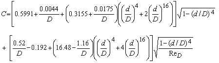
Flange Taps:
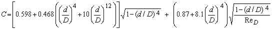
where D is in inches; and d/D, ReD, and C are dimensionless.
Validity (ASME, 2001)
Pipe Diameter D
LMNO Engineering orifice calculation requires 0.635 cm ≤ D ≤ 5.08 cm for both
corner and flange taps.
ASME (2001) suggests 1.2 cm ≤ D ≤ 4 cm for corner taps and 2.5 ≤
D ≤ 4 cm for flange taps.
Diameter ratio d/D
LMNO Engineering and ASME (2001) require 0.1 ≤ d/D ≤ 0.8 for corner taps
and 0.15 ≤ d/D ≤ 0.7 for flange taps.
Reynolds number based on pipe diameter ReD
LMNO Engineering and ASME (2001) require ReD ≥ 1000.
Expansibility e
The orifice equation shown above for expansibility e is valid for P2/P1
≥ 0.8. Our orifice calculation gives a warning message if P2/P1
< 0.8, but still computes answers.
Built-in Properties for Certain Gases
To provide ease of use, our orifice calculation has properties of some gases built-in to the
calculation. The user can select Air, Carbon dioxide, Hydrogen, Methane (natural
gas), Nitrogen, or Oxygen. The density is automatically computed using the ideal gas
law based on the upstream pressure and temperature entered. The dynamic viscosity is
a function of temperature and uses the methodology shown on our Gas
Viscosity page. The isentropic exponent, K, is based on the specific
heat ratio. For methane, the dynamic viscosity value shown in the orifice calculation is
valid for 0 oF ≤ T ≤ 1000 oF. If T<0
oF, then the viscosity value shown and used in the orifice computation is the viscosity at 0
oF. If T>1000 oF, then the viscosity value shown and used
in the orifice computation is the viscosity at 1000 oF (0 oF is -17.8 oC
and 1000 oF is 537.8 oC). For all other gases shown in the
drop-down menu, there is no temperature limitation on the validity of the viscosity.
Dynamic viscosity is essentially independent of pressure.
If you know that your density, viscosity, or isentropic exponent is significantly different than the value shown in the orifice calculation, then you can select "User enters P1, density, viscosity, K" and enter these values manually. Also, if the gas is not listed in our drop-down menu, then you can select "User enters P1, density, viscosity, K" and enter these values manually. K must be > 1. Additionally, values for K can be found in Weast (1985, p. F-11), Perry and Green (1984, p. 3-144), and other sources.
Pressure Loss
w is the static pressure loss occurring from a distance of approximately D
upstream of the orifice to a distance of approximately 6D downstream of the
orifice. It is not the same as differential pressure. Differential pressure is
measured at the exact locations specified in ASME (2001) (shown in the above figures).
Minor Loss Coefficient
Km is computed to allow you to design pipe systems with orifices and
incorporate their head loss. Head loss is computed as h=KmV2pipe/2g.
Standard Volumetric Flow Rate
Standard volumetric flow rate, Qs, is the volumetric flow rate computed
at standard pressure and temperature, Pstd and Tstd
(shown above in variables). Actual flow rate, Qa,
is computed at the gas's actual pressure and temperature. Qs is
useful to users who need to compute (or input) standard flow rate; often pump curves and
flow measurement devices provide standard, rather than actual, flow rate. The
advantage of using standard flow instead of actual flow is that the same device (or pump
curve) can be used for a gas at various temperatures and pressures without re-calibrating
for an infinite range of actual pressures and temperatures. The user can easily
convert standard to actual flow rate if the actual temperature and pressure of the gas are
known; our orifice calculation does this automatically.
Variable Definitions
Dimensions: F=Force, L=Length, M=Mass, T=Time, t=temperature. Note F=M-L/T2.
Bore diameter and throat diameter both refer to d.
A = Area [L2], C = Discharge Coefficient, d = Throat Diameter [L], D = Pipe Diameter [L], e = Gas Expansibility, h = Head Loss [L], k = Equivalent Roughness of Pipe Material [L], K = Gas Isentropic Coefficient, Km = Minor Loss Coefficient, M = Mass Flow Rate [M/T], P1 = Upstream Absolute Pressure [F/L2], P2 = Downstream Absolute Pressure [F/L2], Δp = Differential Pressure [F/L2] = P1-P2, Pstd = Standard Atmospheric Pressure = 14.73 psia = 1.016x10⁵ N/m2, Qa = Actual Volumetric Flow Rate [L3/T], Qs = Volumetric Flow Rate at Standard Pressure and Temperature [L3/T], R = Gas Constant (used to compute gas density) = 8312/W N-m/kg-K, Red = Reynolds Number based on d, ReD = Reynolds Number based on D, T = Gas Temperature [t] (converted automatically to absolute), Tstd = Standard Absolute Temperature = 520oR = 288.9K, V = Velocity [L/T], w = Static Pressure Loss [F/L2], W = Molecular Weight of Gas [gram/mole], β = Ratio d/D, ρ = Gas Density [M/L3], μ = Gas Dynamic Viscosity [F-T/L2]. ν = Gas Kinematic Viscosity [L2/T].
Error Messages
"P2/P1<0.8. Out of range". The equation for expansibility e is only valid for P2/P1≥0.8.
This is a just a warning message; all variables are computed.
For the following error messages, only some variables are computed. For example if orifice throat diameter d is to be computed, then pressure ratio, expansibility, pipe area, pipe velocity, ReD, and some other variables will be computed and shown. However, if ReD is out of range for C to be valid, then C and d (and anything depending on d - such as throat area and throat velocity) will not be computed. If an error message is shown and you think your input is correct, be sure to check that you have selected the correct units for your entries.
"Infeasible input". While none of the inputs alone are out of
range, they collectively result in a physically infeasible situation or a computed
parameter will be out of range (e.g. ReD will be <1000 or d/D
will be out of range) or the throat velocity will exceed the speed of sound (the orifice
calculation is only valid for subsonic velocities).
"P1 and T (abs) must be >0", "Need P1 and
T(abs)>0". Absolute pressure or absolute temperature was entered as
zero or negative. If temperature was entered in C or F, it was internally converted
to absolute temperature.
"Need 0.64<D<5 cm". Pipe diameter must be between 0.635
and 5.08 cm.
"Need 1e-20<Density<1e9 kg/m3". Gas density must be entered
between 10-20 and 109 kg/m3.
"Need 1e-19<Viscosity<1e9 m2/s". Kinematic viscosity must
be in this range. Note that kinematic viscosity is dynamic viscosity divided by
density.
"Need 0.1<d/D<0.8". For orifice corner taps, diameter ratio must be
in this range.
"Need 0.15<d/D<0.7". For orifice flange taps, diameter ratio must
be in this range.
"Need K >1". Isentropic exponent was entered as ≤ 1.
"M or Q, and d must be >0". Mass flow rate, volumetric
flow rates, and/or orifice diameter were entered as zero or negative.
"Need Δp > 0". Orifice differential pressure must be positive.
"Need Δp < P1". Orifice differential pressure cannot
exceed P1; this would cause P2 (absolute) to be
<0 which is impossible.
"M or Q, and Δp must be >0". Mass flow rate, volumetric
flow rates, and/or differential pressure were entered as zero or negative
"Need ReD>1000". ReD must be at
least 1000.
• Try the simpler orifice calculation on our Bernoulli page if your parameters (for instance d/D, D, or ReD) are out of range. It is not as accurate, but won't give "parameter out of range" error messages.
References
American Society of Mechanical Engineers (ASME). 2001. Measurement of fluid
flow using small bore precision orifice meters. ASME MFC-14M-2001.
Perry, R. H. and D. W. Green (editors). 1984. Perry's Chemical Engineers' Handbook. McGraw-Hill Book Co. 6th ed.
Weast, R. C. (editor). 1985. CRC Handbook of Chemistry and Physics. Chemical Rubber Company. 65th ed.
© 2002-2026 LMNO Engineering, Research, and Software, Ltd. All rights reserved.
LMNO Engineering, Research, and Software, Ltd.
7860 Angel Ridge Rd. Athens, Ohio 45701 USA Phone: (740) 707‑2614
LMNO@LMNOeng.com
https://www.LMNOeng.com