
Gas Tank Depressurization Blowdown Time Diagram (Unsteady Gas Flow from a Tank)
Gas in a tank is at a known initial pressure. The tank pressure drops when gas is allowed to exit the tank to the atmosphere. The final pressure in the tank is entered by the user. The time to reach this pressure is computed. The gas flow through the opening can be choked (sonic) or subsonic. The calculation uses two methods: Isothermal or isentropic. Isothermal means that the temperature in the tank and through the hole remain at the initial tank temperature as the pressure drops. Isentropic means that the temperature in the tank and through the hole change as pressure drops.
Units: atm=atmosphere, cm=centimeter, ft=foot, g=gram, gallon is U.S. gallon, hr=hour, k=kilo (1000), kPa=kiloPascal, kg=kilogram, lb=pound, m=meter, min=minute, mm=millimeter, M=Mega (million, 106), MPa=MegaPascal, N=Newton (force), N/m2=Newton per square meter (same as Pascal), Pa=Pascal, s=second, psf=pound per square foot (lb/ft2), psia=pound per square inch absolute, yr=year.
Topics: Introduction Equations Variables Messages References Screen Captures of Calculation Results, Graph, Table
Introduction
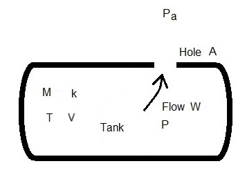
The tank has a volume V and contains gas of molecular weight M and specific heat ratio k. Ambient pressure Pa outside of the tank is constant. Gas exits a hole of area A. The tank has an initial pressure Pi and final pressure Pf. Pressure P in tank varies with time. Temperature T is constant for the isothermal model. Temperature T varies with time in the isentropic model. Mass flow rate W out of tank varies with time as tank pressure drops from Pi to Pf.
If gas discharges slowly from the tank, then the isothermal model is more valid since heat transfer has time to occur. If the gas discharges rapidly, then the isentropic model is more valid since heat transfer does not have time to occur. Isentropic means adiabatic and reversible; there is no net transfer of heat in an isentropic process. Gas discharges faster using the isentropic equations. The equations give the time to depressurize for both processes. The equations do not tell you which process is appropriate for your situation. Since the two cases are the two extreme conditions (Saad, 1993, p. 106), the results provide the bounds for the depressurization time.
The calculator also includes a graph of pressure versus time for the isothermal and isentropic methods.
Equations
Back to Calculation
Choked flow equations are from Saad (1985, pp. 103-106).
Define choked flow constants for isothermal and isentropic flow:


Time to achieve Pf if isothermal (T = Ti = constant) and if isentropic:


Compute critical pressure:

If Pf > Pc, then flow is always choked.
For isentropic flow (from above):
To determine how pressure varies with time for isentropic flow, Pf [renamed P(t)] can be determined as a function of time:

For isothermal flow (from above):
To determine how pressure varies with time for isothermal flow, Pf [renamed P(t)] can be determined as a function of time:
![]()
Subsonic Flow
When flow is subsonic (either becomes subsonic or starts subsonic), the equation from Daugherty et al. (1985, p. 275) is used:
 and
and
![]()
Note that the equation for W is the same as in our Gas Leak Rate Calculator link except that the gas leak rate calculator includes a discharge coefficient. The equation above does not include a discharge coefficient because discharge coefficient likely varies as pressure drops when the gas flows out of the tank. Thus, a single discharge coefficient is not valid for the entire range. Saad (1985) and other references leave out the discharge coefficient implying that it is 1.0 for the duration of the depressurization.
The above equation is for steady flow. Since we are interested in unsteady flow, the derivative of flow with time is utilized. W is mass flow rate which is the change in mass per time:
![]()
Ideal gas equation of state:
![]()
Since the tank has a constant volume:
 Then:
Then:

Subsonic Isentropic Flow:
From Saad (1985, p. 104) for isentropic flow:
![]()
Therefore, dP/dt is obtained:

Note the minus sign for the second term above since mass is lost as pressure decreases. Substituting:
![]()
We obtain:

Continuing algebra:

And:

Therefore for subsonic isentropic flow:

If flow is also isothermal, T is constant and:
![]()
With:
![]()
Since isothermal:
![]()
Substituting one obtains:

Then for subsonic isothermal flow:

The dP/dt equations for isentropic and isothermal are difficult to solve analytically. Define Cs,isen:

Then for isentropic subsonic flow:

Define Cs,iso:

Then for isothermal subsonic flow:

Write the differentials as differences and solve numerically. For subsonic isentropic flow, let Cs=Cs,isen and for subsonic isothermal flow, let Cs=Cs,iso. Thus:

Thus for a small pressure change ΔP, the time interval for that pressure change to happen is:

Variables
Variables (shown in SI units but a variety of units can be used in calculator):
A = Area of opening, m2.
Cc,isen = Constant for choked, isentropic flow, s.
Cc,iso = Constant for choked, isothermal flow, s.
Cs,isen = Constant for subsonic, isentropic flow, s-1-K-0.5.
Cs,iso = Constant for subsonic, isothermal flow, s-1-K-0.5.
Cs = Constant for subsonic flow.
k = Gas specific heat ratio.
m = Mass of gas in tank (varies with time), kg.
M = Gas molecular weight, kg/mole.
P = Pressure (varies with time), N/m2 absolute.
Pa = Ambient pressure, N/m2 absolute.
Pc = Critical pressure, N/m2 absolute.
Pf = Final pressure in tank, N/m2 absolute.
Pi = Initial pressure in tank, N/m2 absolute.
R = Gas constant for the selected gas, N-m/kg-K.
Ru = Universal gas constant = 8.3144126 N-m/mole-K.
t = Time, s.
tc,isen = Time to achieve Pf if choked and isentropic, s.
tc,iso = Time to achieve Pf if choked and isotropic, s.
Δts = Subsonic change in time, s.
T = Temperature in tank (constant in isothermal case, varies if isentropic), K.
Ti = Initial temperature in tank, K.
V = Tank volume, m3.
W = Mass flow rate out hole (varies with time), kg/s.
Error Messages
Back to Calculation
"Need S and M ≥ 1e-50", "Need k ≥ 1.0000001", "Need d ≥ 1e-50", "Need A ≥ 1e-50", "Need Pi ≥ 1e-50", "Need Pf ≥ 1e-50", "Need Pa ≥ 1e-50", "Need Pi > Pf", "Need Pf ≥ Pa", "Need V ≥ 1e-50", "Need Ti ≥ 1e-50", "Need Pf / Pi≥ 1e-15". "Invalid input" means letters or spaces were entered.
References
Back to Calculation
Chemical Rubber Company (CRC). (1983). CRC Handbook of Chemistry and Physics. Weast, Robert C., editor. 63rd edition. CRC Press, Inc. Boca Raton, Florida.
Daugherty, R. L., Franzini, J. B. and Finnemore, E. J. (1985). Fluid Mechanics with Engineering Applications. McGraw-Hill. 8ed.
Engineers Edge. (2020). Gas discharge rate atmosphere from a pressure vessel. Retrieved from https://www.engineersedge.com/pressure,045vessel/gas_discharge_rate_14170.htm
Gas Processors Suppliers Association (GPSA). (1998). Engineering Data Book (fps [foot-pound-second] version). Gas Processors Association. 11ed.
Kayser, J. C. and Shambaugh, R. L. (1991). Discharge coefficients for compressible flow through small-diameter orifices and convergent nozzles. Chemical Engineering Science. v. 46(7). pp. 1697-1711.
Perry, R. H. and D. W. Green, editors. (1984). Perry's Chemical Engineers' Handbook. McGraw-Hill, Inc. 6ed.
Munson, B.R., D. F. Young, and T. H. Okiishi. (1998). Fundamentals of Fluid Mechanics. John Wiley and Sons, Inc. 3ed.
Saad, M. A. (1993). Compressible Fluid Flow. Prentice Hall. 2ed.
Shapiro, A. H. (1953). The Dynamics and Thermodynamics of Compressible Fluid Flow. The Ronald Press Co. Volume 1.
White, F. M. (2003). Fluid Mechanics. McGraw-Hill. 5ed.
Screen Captures of Calculation Results, Graph, Table
Back to Calculation
Calculator image if registered user:

Graph image if registered user:

Table image if registered user:

Comma separated values to copy/paste into spreadsheet:
Pressure (psia), Isothermal Time (min), Isentropic Time (min)
60,0,0
59.411765,0.04611092,0.032959561
58.823529,0.092680662,0.0662942
58.235294,0.13971845,0.100012
57.647059,0.18723379,0.13412131
57.058824,0.23523647,0.16863073
56.470588,0.2837366,0.20354916
55.882353,0.33274459,0.23888578
55.294118,0.3822712,0.27465009
54.705882,0.43232751,0.31085188
54.117647,0.48292498,0.34750131
53.529412,0.53407544,0.38460887
52.941176,0.58579111,0.4221854
52.352941,0.63808462,0.46024216
51.764706,0.69096903,0.49879078
51.176471,0.74445785,0.53784331
50.588235,0.79856504,0.57741225
50,0.85330509,0.61751055
49.411765,0.90869296,0.65815164
48.823529,0.96474417,0.69934948
48.235294,1.0214748,0.74111853
47.647059,1.0789016,0.78347382
47.058824,1.1370417,0.82643098
46.470588,1.1959132,0.87000625
45.882353,1.2555346,0.9142165
45.294118,1.3159254,0.95907932
44.705882,1.3771056,1.004613
44.117647,1.4390962,1.0508366
43.529412,1.5019189,1.09777
42.941176,1.5655963,1.1454339
42.352941,1.6301521,1.1938499
41.764706,1.6956108,1.2430406
41.176471,1.761998,1.2930296
40.588235,1.8293405,1.3438414
40,1.8976661,1.3955019
39.411765,1.967004,1.448038
38.823529,2.0373846,1.501478
38.235294,2.1088397,1.5558515
37.647059,2.1814027,1.6111895
37.058824,2.2551085,1.6675246
36.470588,2.3299936,1.7248911
35.882353,2.4060964,1.7833249
35.294118,2.4834572,1.8428639
34.705882,2.5621182,1.9035479
34.117647,2.642124,1.9654189
33.529412,2.7235211,2.0285213
32.941176,2.8063591,2.0929018
32.352941,2.8906897,2.1586097
31.764706,2.9765677,2.2256974
31.176471,3.064051,2.2942202
30.588235,3.1532007,2.3642368
30,3.2440816,2.4358094
29.411765,3.3367623,2.5090041
28.823529,3.4313154,2.5838913
28.235294,3.5278182,2.6605459
27.647059,3.6290344,2.7411826
27.058824,3.7402041,2.8300071
26.470588,3.8559715,2.9227926
25.882353,3.976982,3.0200887
25.294118,4.1040466,3.1225844
24.705882,4.2382082,3.2311648
24.117647,4.3808466,3.346999
23.529412,4.5338542,3.4716874
22.941176,4.6999486,3.6075248
22.352941,4.8832869,3.7580155
21.764706,5.0908303,3.9290173
21.176471,5.3360276,4.131828
20.588235,5.6528965,4.3949734
20,6.2702394,4.9099052
© 2025-2026 LMNO Engineering, Research, and Software, Ltd. All rights reserved.
LMNO Engineering, Research, and Software, Ltd.
7860 Angel Ridge Rd. Athens, Ohio 45701 USA Phone: (740) 707‑2614
LMNO@LMNOeng.com
https://www.LMNOeng.com