
Units: cm=centimeter, cfs=cubic feet per second, ft=feet, gpm=US gallons per minute, gph=US gallons per hour, gpd=US gallons per day, m=meters, MGD=Millions of US gallons per day, s=second
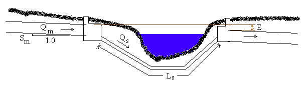
Summary: Inverted siphons (also called depressed sewers) allow stormwater or wastewater sewers to pass under obstructions such as rivers. Our inverted siphon calculation allows up to five parallel siphons to go under the river. Unlike the main sewer pipe, the siphon pipes flow under pressure and must have flow velocities greater than 3 ft/s (0.9 m/s) to keep material suspended. Therefore, several siphons having smaller diameters than the main sewer may be required. The calculation computes siphon diameters (or siphon flows), velocities, inlet chamber wall heights, and siphon invert elevations.
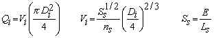
Overall Diagram
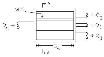
Plan view of inlet chamber (3 siphons)
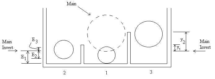
Section A-A (exploded scale)
For ease of fabrication, all siphon inverts can be located at the elevation of the lowest siphon invert.
Links on this page: Introduction Equations Variables Manning n coefficients Glossary Error messages and validity References
Introduction
Stormwater and wastewater sewers often encounter obstructions such as rivers, other pipes, subways, tunnels, or valleys. To pass these obstructions, a common method is for the sewer pipe to drop sharply, then run horizontal under the obstruction, and finally rise to the desired elevation. The piping going under the obstruction is traditionally called an "inverted siphon", but since the pipe is not actually acting as a siphon, a better term is "depressed sewer" (Metcalf and Eddy, 1981).
Unlike the main sewer pipe, the siphon pipe(s) flow under pressure. Special care must be taken in inverted siphon design since losses are greater for pressurized flow, and the velocity in each siphon pipe must be at least 3 ft/s (0.9 m/s) for sewage or 4 ft/s (1.2 m/s) for storm water (Metcalf and Eddy, 1981). Therefore, even if there is only one main sewer pipe, several siphons may be required. If minor losses due to bends or elbows in the siphon are significant compared to the siphon length, include the equivalent length of the elbows. Increase the siphon length (Ls) so that Ls is the physical length of a siphon plus the equivalent length of minor losses due to elbows in siphon.
Equations and Methodology
Back to calculation
Equations are primarily from Metcalf and Eddy (1981) but are supplemented by equations in Chow (1959) and Viessman and Hammer (1998). Note that Manning's equation is empirical, and its form in the following equations requires use of meters and seconds for the units.
Compute the maximum flow in the main sewer pipe using Manning's equation for full pipe flow:
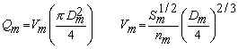
Compute the diameter of each siphon, Di, or the flow through each siphon, Qi, using Manning's equation for full pipe flow through each siphon:
Compute the wall heights, yj (relative to main invert), in the inlet box. The walls separate the siphons from each other. The wall heights are the same height as the water depths, yj, in the main pipe corresponding to the discharge through the siphons. Here, Qj=1 is the discharge through siphon 1, Qj=2 is the discharge through siphons 1 and 2, and so on. Manning's equation for a partially full main pipe is used, but is solved backwards (numerically) in order to compute yj. We allow up to five siphons (four walls).
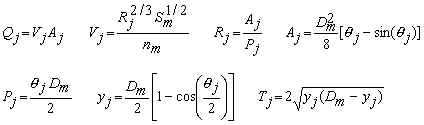
Compute the siphon invert elevations in the inlet chamber. According to Metcalf and Eddy (1981), there is no loss in the inlet box for flow going from the main culvert to the first siphon since the flow travels in a straight path. However, for siphons 2 through n the flow must turn 90o to go over the chamber wall (a head loss of 1.5 velocity heads) and has an additional head loss of one velocity head as the flow enters siphon i. Therefore, for i=2 to n siphons and j=2 to n-1 walls:
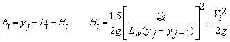
where Ei is relative to the invert of the main pipe. Note that for the first siphon, Hi=0, and for the last siphon yj is replaced by Dm. Often, all siphon inverts are located at the same elevation (the elevation of the lowest siphon) for ease of construction.
Variables
Back to calculation
Aj = Flow area in the main pipe for computing height of wall j [m2].
Di = Diameter of siphon i [m].
Dm = Diameter of main pipe [m].
E = Main invert's elevation drop from inlet chamber to outlet chamber [m].
Used to compute hydraulic grade line, Ss, for siphon pipes.
Ei = Siphon i inlet invert elevation relative to invert of main culvert
[m]. These are maximum elevations. Any siphon can be placed lower than Ei.
For ease of fabrication, all siphon inverts are often placed at the elevation of
the lowest siphon invert.
Hi = Head loss for flow from main pipe to siphon i [m].
Ls = Total length of one siphon [m]. Assumes all siphons are
approximately the same length.
Lw = Wall length inside inlet chamber [m]. Also known as weir
length.
nm = Manning's n coefficient of main pipe.
ns = Manning's n coefficient for the siphon pipes.
Pj = Wetted perimeter of main pipe for computing height of wall j [m].
Qi = Flow rate (discharge) through siphon i [m3/s].
Qm = Flow rate (discharge) through main pipe when flowing full [m3/s].
Qj = Flow rate (discharge) through main pipe where j represents the sum
of siphons 1 through j [m3/s]. For instance, if j=3, then Qj=Q1+Q2+Q3. Used to compute height of wall j.
Rj = Hydraulic radius of main pipe for computing height of wall j [m].
Sm = Slope of main pipe [m/m]. Vertical/Horizontal.
Ss = Allowable hydraulic grade line for siphon pipes [m/m]
Tj = Top width of main pipe for computing height of wall j [m].
Vi = Velocity of water flowing through siphon i [m/s].
Vm = Velocity of water flowing through main pipe when flowing full
[m/s].
Vj = Velocity of water flowing through main pipe for computing wall
heights j [m/s].
yj = Water depth in main pipe for computing wall heights j [m]. yj
is measured relative to the main invert. Therefore, if the bottom of the inlet
chamber is below the main invert, the wall will actually be yj plus the
elevation difference between the main invert and the bottom of the chamber. In the
figure titled "Section A-A" at the top of this page, the physical wall heights
are y1+E1 and y2+E1, since siphon 1 has the
lowest invert of the three siphons shown in the figure.
π = Greek letter "pi" = 3.1415926...
θj = Greek letter "theta". Angle for computing height of wall j [radians].
Manning n Coefficients
Back to calculation
Manning n values are from Metcalf and Eddy (1981), AISI (1980), and footnoted items in references for pipes in good condition.
| Pipe Material | Manning n | Pipe Material | Manning n |
| Uncoated cast iron | 0.013 | Coated cast iron | 0.012 |
| Commercial wrought iron - black | 0.013 | Commercial wrought iron - galvanized | 0.014 |
| Smooth brass and glass | 0.010 | Smooth lockbar and welded "OD" | 0.011 |
| Riveted and spiral steel pipe | 0.015 | Corrugated Metal | 0.022* |
| Common clay drainage tile | 0.012 | Vitrified sewer pipe | 0.013 |
| Brick in cement mortar, brick sewers | 0.013 | Glazed brickwork | 0.012 |
| Cement mortar surfaces | 0.012 | Neat cement surfaces | 0.011 |
| Wood stave pipe | 0.011 | Concrete pipe | 0.013 |
| Corrugated Polyethylene (PE) with smooth inner walls a,b | 0.009-0.015 | ||
| Corrugated Polyethylene (PE) with corrugated inner walls c | 0.018-0.025 | ||
| Polyvinyl Chloride (PVC) with smooth inner walls d,e | 0.009-0.011 | ||
* Corrugated metal pipe n value can vary significantly with pipe diameter and type of corrugations (values can range from 0.012 to 0.033) - AISI (1980).
Glossary
Back to calculation
Inlet chamber - usually concrete manhole where main culvert branches into several siphon pipes.
Invert - inside bottom of pipe.
Main - culvert through which flow occurs before and after the siphon.
Siphon - pipe or pipes flowing full and under pressure which go underneath the
obstruction. Not siphons by the true definition. True siphons flow uphill then
back down. Siphons used here go down then back up.
Error Messages and Validity for Calculation
Back to calculation
Initial input checks:
"Need 1e-9<Dm<1e9 m". Main culvert diameter must
be between these limits.
"Need 1e-9<E<1e9 m". Elevation drop from the inlet chamber
to the outlet chamber must be between these limits.
"Need 1e-9<Ls<1e9 m". The length of each siphon
pipe must be between these limits.
"Need 1e-9<Lw<1e9 m". The lengths of the inlet
chamber walls must be between these limits.
"Need 1e-9<Sm<1e9". The slope of the main culvert must
be between these limits.
"Need 1e-9<Main n<1e9", "Need 1e-9<Siphon n<1e9". The Mannings n values for the main culvert and siphons must be between these limits.
"Need 1e-9<D1<1e9 m", "Need 1e-9<D2<1e9 m", "Need 1e-9<D3<1e9 m", "Need 1e-9<D4<1e9 m", "Need 1e-9<D5<1e9 m". If siphon diameters are input, they must be between these limits.
"Need 1e-9<Q1<1e9 m3/s", "Need 1e-9<Q2<1e9 m3/s", "Need 1e-9<Q3<1e9 m3/s", "Need 1e-9<Q4<1e9 m3/s". If siphon flows are input, the flows must be between these limits.
Run-time errors:
"Need 1e-9<Qm<1e9 m3/s". Discharge computed in main culvert must be in this range for calculations to continue.
"Need siphon Q>0". If diameters are being computed, the flowrate through the last siphon is automatically computed such that the sum of the flow through all siphons is equal to the discharge through the main culvert. If the siphon flows input by the user exceed the discharge in the main culvert, then the flow in the last siphon will be negative, which will generate the error message. You should reduce the flows in the siphons so that there is positive flow in the last siphon. Or, you could reduce the number of culverts.
"Siphons under-designed". Shown only if siphon flows are being computed and Qs/Qm<0.95. You need to increase the siphon diameters. This message will not be generated if diameters are being computed - because diameters are computed so that the total flow through the siphons is exactly equal to the discharge through the main culvert.
"Siphons over-designed". Shown only if siphon flows are being computed and Qs/Qm>1.05. Since wall heights cannot be computed for flows grossly exceeding that of the main culvert, the calculation stops. You need to decrease the siphon diameters. This message will not be generated if diameters are being computed - because diameters are computed so that the total flow through the siphons is exactly equal to the discharge through the main culvert.
References and Bibliography
Back to calculation
AISI (American Iron and Steel Institute). 1980. Modern Sewer Design.
a Barfuss, Steven and J. Paul Tullis. Friction factor test on high density polyethylene pipe. Hydraulics Report No. 208. Utah Water Research Laboratory, Utah State University. Logan, Utah. 1988.
c Barfuss, Steven and J. Paul Tullis. Friction factor test on high density polyethylene pipe. Hydraulics Report No. 208. Utah Water Research Laboratory, Utah State University. Logan, Utah. 1994.
e Bishop, R.R. and R.W. Jeppson. Hydraulic characteristics of PVC sewer pipe in sanitary sewers. Utah State University. Logan, Utah. September 1975.
Chow, V. T. 1959. Open-Channel Hydraulics. McGraw-Hill, Inc. (the classic text)
Hammer, M. J. and M. J. Hammer, Jr. 1996. Water and Wastewater Technology. Prentice Hall, 3ed.
Metcalf and Eddy, Inc. 1981. G. Tchobanoglous, editor. Wastewater Engineering: Collection and Pumping of Wastewater. McGraw-Hill, Inc. (Note that there are some errors in the invert elevations computed on p. 175.)
d Neale, L.C. and R.E. Price. Flow characteristics of PVC sewer pipe. Journal of the Sanitary Engineering Division, Div. Proc 90SA3, ASCE. pp. 109-129. 1964.
b Tullis, J. Paul, R.K. Watkins, and S. L. Barfuss. Innovative new drainage pipe. Proceedings of the International Conference on Pipeline Design and Installation, ASCE. March 25-27, 1990.
Viessman, W. and M. J. Hammer. 1998. Water Supply and Pollution Control. Addison-Wesley, 6ed.
© 2000-2026 LMNO Engineering, Research, and Software, Ltd. All rights reserved.
LMNO Engineering, Research, and Software, Ltd.
7860 Angel Ridge Rd. Athens, Ohio 45701 USA Phone: (740) 707‑2614
LMNO@LMNOeng.com
https://www.LMNOeng.com