
Units: bbls/day=barrels/day (1 bbl=42 US gallons), cfm=ft3/min, cfs=ft3/s, cm=centimeter, cP=centipoise, cSt=centistoke, deg=degrees, in H2O=inch water at 60F, in Hg=inch mercury at 60F, ft=foot, ft H2O=ft water at 60F, g=gram, gpd=gallon (US)/day, gph=gallon (US)/hr, gpm=gallon (US)/min, hr=hour, kg=kilogram, km=kilometer, kW=kiloWatt, lb=pound, m=meter, mbar=millibar, mm=millimeter, mm Hg=mm mercury at 0C, min=minute, N=Newton, Pa=Pascal (1 Pa=1 N/m2), s=second
Topics on this page: Introduction Equations Minor loss coefficients Built-in fluid and material properties Variables Error Messages References
Introduction
The LMNO Engineering Bypass Loop Calculator will help determine how to get a desired flowrate Qby through a bypass piping loop. It was developed in conjunction with Anton Paar USA, which sells transducers for measuring the density of a flowing liquid or gas. For proper operation, the transducers require the flow rate to be within a certain range. Often an existing pipe installation carries too much flow for the transducer; therefore, a bypass loop having a lower flow rate is designed, and the transducer is installed in the loop. The calculation is general enough to model many other situations where a bypass loop is needed.
The calculation requires fluid density and viscosity, pipe materials, system pressure, system flowrate, desired bypass flowrate, pipe diameters and lengths, elevations of various locations in the system, and minor losses coefficients representing pipe bends, valves etc. The program computes pumping requirements (if any), head losses, and pressures throughout the system. If you wish to use a constricting device such as a venturi to force flow through the bypass loop, then also enter the converging and diverging angles of the venturi and the venturi throat diameter. The calculation computes head losses, pressures throughout the system, and the length of venturi throat required to achieve the desired bypass flow rate.
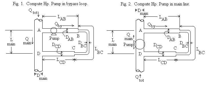
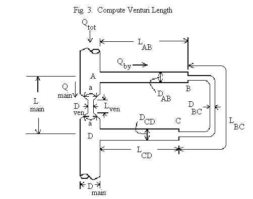
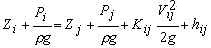
To summarize, the desired bypass flow rate Qby can be achieved by drawing fluid out of the main line with a bypass pump (Fig. 1), forcing the fluid into the bypass loop with a pump in the main line (Fig. 2), or forcing fluid into the bypass loop by adding a constriction to the main line (Fig. 3 - shows a venturi restriction device). Each of these scenarios is selectable by clicking on the drop-down menu which initially reads "Hp in bypass" (implying that a pump will be installed in the bypass loop and the calculation will compute the required pump head, Hp).
The program does not check if input or computed pressures are physically impossible, such as approaching or lower than a complete vacuum. The calculation does not check if velocities are unreasonable, such as gases flowing at over half the speed of sound which would require use of compressible gas equations.
Equations in Bypass Flow Calculator
Our bypass flow calculation uses the incompressible steady state energy equation, Darcy-Weisbach or Hazen-Williams pipe major (friction) losses, and minor losses to simulate valves, pipe bends, etc. The losses through the contracting and expanding portions of the venturi are from Crane (1988).
Energy Equation
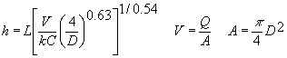
The subscripts i and j refer to the points A, B, C, and D in the above figures. Vij , Kij , and hij refer to the velocity in the pipe between points i and j, the minor losses in the pipe ij, and the major (friction) loss in the pipe ij. Thus, four energy equations are written to solve a problem: energy from A to B, energy from B to C, energy from C to D, and energy from A to D (D to A if the pump is in the main line).
If a pump is present in pipe ij, the term Hp is added to the left hand side of the above equation. If the pump is in the bypass line, it is placed between A and B and is included in the energy equation from A to B. If the pump is in the main line, then it is placed between D and A and is included in the energy equation from D to A. If the venturi length is computed, no pumps are used. Instead, losses through the venturi expansion, contraction, and throat are computed. Loss through the venturi throat is a major loss and is computed just like the other major losses except that it uses the venturi throat diameter, length, and roughness.
Major (friction) Losses, hij
The calculation gives you a choice of computing friction losses hij using the Darcy-Weisbach (DW) or the Hazen-Williams (HW) method. The DW method can be used for any liquid or gas while the HW method can only be used for water at temperatures typical of municipal water supply systems (4-25oC, 40-75oF). HW losses can be selected with the menu that initially says "Roughness, e (mm):". The following equations are used (subscripts i and j are dropped for simplicity):
Hazen Williams equation (Mays, 1999; Streeter et al., 1998; Viessman and Hammer, 1993) where k=0.85 for meter and seconds units or 1.318 for feet and seconds units:
Darcy Weisbach equation (Mays, 1999; Munson et al., 1998; Streeter et al., 1998):
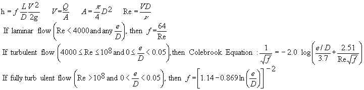
where "log" is base 10 logarithm and "ln" is natural logarithm. Variable definitions are listed below.
Venturi losses
The length of the contracting portion of the venturi is:
Lcon=(Dmain - Dven ) / [2 tan (a/2)]
The length of the diverging portion of the venturi Ldiv is the same as Lcon since the venturi is assumed to have the same contracting and diverging angle a.
Minor losses through the contracting and diverging portions of the venturi are based on Crane (1988), where the head loss is KV 2ven /(2g) and Vven is the velocity through the venturi tube having diameter, Dven.
Contracting portion of venturi, a ≤ 45o: Kcon = 0.8 [1 - (Dven/Dmain ) 2] sin(a/2)
Contracting portion of venturi, 45o < a ≤ 180o: Kcon = 0.5 [1 - (Dven/Dmain ) 2] [sin(a/2)]1/2
Diverging portion of venturi, a ≤ 45o: Kdiv = 2.6 [1 - (Dven/Dmain ) 2]2 sin(a/2)
Diverging portion of venturi, 45o < a ≤ 180o: Kdiv = [1 - (Dven/Dmain ) 2]2
Minor Loss Coefficients, K
The following minor loss coefficient table was assembled from data shown in Mays (1999), Munson et al. (1998), and Streeter et al. (1998). Minor losses for the contracting and diverging portion of the venturi are shown in the above section.
| Fitting | K | Fitting | K |
| Valves: | Elbows: | ||
| Globe, fully open | 10 | Regular 90°, flanged | 0.3 |
| Angle, fully open | 2 | Regular 90°, threaded | 1.5 |
| Gate, fully open | 0.15 | Long radius 90°, flanged | 0.2 |
| Gate 1/4 closed | 0.26 | Long radius 90°, threaded | 0.7 |
| Gate, 1/2 closed | 2.1 | Long radius 45°, threaded | 0.2 |
| Gate, 3/4 closed | 17 | Regular 45°, threaded | 0.4 |
| Swing check, forward flow | 2 | ||
| Swing check, backward flow | infinity | Tees: | |
| Line flow, flanged | 0.2 | ||
| 180o return bends: | Line flow, threaded | 0.9 | |
| Flanged | 0.2 | Branch flow, flanged | 1.0 |
| Threaded | 1.5 | Branch flow, threaded | 2.0 |
Built-in fluid and material properties
The user may manually enter fluid density and viscosity or select one of the common liquids or gases from the drop-down menu. Density and viscosity for the built-in fluids were obtained from Munson et al. (1998). Likewise, the user may manually enter material roughness or Hazen-Williams C, or select one of the common pipe materials listed in the other drop-down menu. Surface roughnesses for the built-in materials were compiled from Munson et al. (1998), Streeter et al. (1998), and Mays (1999).
Variables in Bypass Flow Calculator
[ ] indicates units: F=force, L=length, P=pressure, T=time
Variables in the bypass calculator can be entered in many different units by clicking on the drop-down menus in the calculation. Viscosity units can be a bit confusing since some of them are dynamic viscosity (cP, poise, N-s/m2 (same as kg/m-s), lb-s/ft2 (same as slug/ft-s) and some are kinematic viscosity (cSt, stoke (same as cm2/s), ft2/s, m2/s). All viscosities are internally converted by the pipe network analysis calculator to kinematic viscosity in SI units (m2/s). If necessary, the equation Kinematic viscosity = Dynamic viscosity/Mass density is used internally.
a = Venturi inlet and outlet angle [degrees].
A = Pipe area [L2].
C = Hazen Williams coefficient. Selectable as last item in drop-down menu saying "Roughness, e".
D = Pipe inside diameter [L].
DAB = Inside diameter of pipe section AB [L].
DBC = Inside diameter of pipe section BC [L].
DCD = Inside diameter of pipe section CD [L].
Dmain = Inside diameter of main pipe [L].
Dven = Inside diameter of venturi throat [L].
e = Pipe roughness [L]. Used for Darcy-Weisbach friction loss equation.
f = Moody friction factor, used in Darcy Weisbach friction loss equation.
g = Acceleration due to gravity = 32.174 ft/s2 = 9.8066 m/s2.
h = Major (friction) loss in pipe [L]. Can also be expressed in pressure units [P].
hij = Major (friction) loss in pipe section ij [L]. Can also be expressed in pressure units [P].
Hp = Pump head [L]. Also known as total dynamic head.
Can also be computed in power units such as horsepower or Watts by clicking on its drop-down menu.
Power=(mass density)(g)(Q)(Hp) where Q is the flowrate
through the pump.
i = Subscript indicating location, such as A, B, C, or D in Figures 1, 2, and 3 above.
j = Subscript indicating location, such as A, B, C, or D in Figures 1, 2, and 3 above.
k = Constant in Hazen Williams equation for computing h.
K = Minor loss coefficient for valves, pipe bends, elbows, expansions, contractions. If a venturi is used,
K for main pipe AD represents only those minor losses in the pipe having diameter DAD,
and not the minor losses in any portion of the venturi. Also, if a venturi is used, K shown in the calculation
for the venturi is the computed sum Kcon + Kdiv.
Kcon = Minor loss coefficient computed for contracting portion of venturi.
Kdiv = Minor loss coefficient computed for diverging portion of venturi.
Also, if a venturi is used, K for the venturi is the computed sum of the minor loss coefficients
in the converging and diverging portions of the venturi (Kcon + Kdiv
in the equations above).
Kij = Sum of minor loss coefficients in pipe section ij.
L = Pipe length [L].
LAB = Pipe length from A to B [L]. LBC = Pipe length from B to C [L].
LCD = Pipe length from C to D [L].
Lcon = Length of contracting portion of venturi [L].
Ldiv = Length of diverging portion of venturi [L].
Lmain = Length of main pipe from A to D [L].
Lven = Length of venturi throat [L]; that is, the portion having diameter Dven.
Pi = Pressure at location i [P]. Can also be expressed in length units [L], as in meters of fluid.
Q = Flow rate [L3/T]. Also known as discharge or capacity.
Qby = Flow rate in bypass loop [L3/T].
Qmain = Flow rate through main pipe AD [L3/T].
Qtot = Total flowrate [L3/T]. For Figs. 1 and 3,
Qtot=Qmain+Qby. For Fig. 2,
Qtot=Qmain-Qby.
Re = Reynolds number.
V = Velocity in pipe [L/T].
Vij = Velocity in pipe ij [L/T].
Zi = Elevation of location i [L].
ν = Kinematic viscosity of fluid [L2/T]. Greek letter "nu". Used in Reynolds number.
Note that kinematic viscosity is equivalent to dynamic (or absolute) viscosity divided by mass density.
Error Messages in Bypass Flow Calculator
Initial input checks:
"Need bypass L > 0". The sum LAB + LBC + LCD must be positive.
"Need Cventuri > 0". Hazen-Williams C for the venturi tube must be positive.
"Need eventuri ≥ 0". Darcy-Weisbach roughness e was entered as negative for the ventrui tube.
"Need density > 0". Density must be a positive number.
"Need diameters > 0". Diameters must be positive.
"Need e ≥ 0". Darcy-Weisbach roughness e cannot be negative for any pipe.
"Need bypass L's ≥ 0". Bypass pipe lengths cannot be negative. Two of them can have zero length.
"Need flows > 0". Total flow and bypass flow must be positive.
"Need H-W Coeff > 0". Hazen-Williams C for all pipes must be positive.
"Need K ≥ 0". Minor loss coefficients cannot be negative.
"Need Lmain > 0". Length of main pipe AD must be positive.
"Need Qtot>Qby". For Figs. 1 and 3, total flow must exceed bypass flow.
"Need viscosity > 0". Viscosity must be positive.
"Need 0<Angle≤180". Venturi angle must be in this range.
"Need 0<Dv<Dm". Venturi diameter must be positive and less than the diameter of the main pipe.
"Since H-W: Need Water (20C)". If Hazen-Williams C selected for roughness, then Water (20C) must be selected as the fluid.
Messages after completion of calculation:
"Lm too short". Length of the main pipe AD must be longer to accommodate the computed venturi length.
"Lven < 0". The computed venturi length is negative. The venturi may not be necessary to cause flow through the bypass loop. You might try increasing the diameter of the venturi in order to get a positive value for the length.
"Lven+Lcon+Ldiv > Lm". The computed sum of the venturi length, contraction, and divergence are greater than the length of the main pipe. Increase the length of the main in order to accommodate the venturi, contraction, and divergence.
"No pump, Hp≤0". Pump head was computed as less than or equal to 0. A pump is not needed to achieve the desired bypass flowrate. The negative value means that the pump is functioning as a turbine generating energy.
"Re or e/D out of range". Reynolds number and e/D must be in the ranges shown above in Darcy Weisbach equation for all pipes.
References for Bypass Flow Calculation
Crane Company. 1988. Flow of Fluids through Valves, Fittings, and Pipe. Technical Paper No. 410 (TP 410).
Mays, L. W. editor. 1999. Hydraulic Design Handbook. McGraw-Hill Book Co.
Munson, B.R., D. F. Young, and T. H. Okiishi. 1998. Fundamentals of Fluid Mechanics. John Wiley and Sons, Inc. 3ed.
Streeter, V. L., E. B. Wylie, and K. W. Bedford. 1998. Fluid Mechanics. WCB/McGraw-Hill. 9ed.
Viessman, W. and M. J. Hammer. 1993. Water Supply and Pollution Control. HarperCollins College Publishers. 5ed.
© 2002-2026 LMNO Engineering, Research, and Software, Ltd. All rights reserved.
LMNO Engineering, Research, and Software, Ltd.
7860 Angel Ridge Rd. Athens, Ohio 45701 USA Phone: (740) 707‑2614
LMNO@LMNOeng.com
https://www.LMNOeng.com