
Units: cfs=cubic foot per second, cm=centimeter, ft=foot, gal=U.S. gallon, gpd=U.S. gallon per day, gpm=U.S. gallon per mimute, hp=horsepower, lb=pound, m=meter, min=minute, N=Newton, Pa=Pascal, psi=lb/inch2, s=second
Topics: Piping Scenarios Equations and Methodology Variables Hazen-Williams Coefficients Minor Loss Coefficients Error Messages
Introduction
The Hazen-Williams equation for major (friction) losses is commonly used by engineers for designing and analyzing piping systems carrying water at typical temperatures of municipal water supplies (40 to 75 oF; 4 to 25 oC). A pump curve is incorporated into the pump operating point calculator to simulate flows containing centrifugal pumps or other pumps that have a pump curve. To keep the pump operating point calculator's input relatively simple, we only require you to enter two points on the pump curve - flow at zero head and head at zero flow. A parabolic curve is then formed between the two points as shown in Equations below. The pump operating point calculator also asks for information specifically about the pipe on the suction side of the pump. This information is used to compute the net positive suction head available (NPSHA). For a pump to properly function, the NPSHA must be greater than the NPSH required by the pump (obtained from the pump manufacturer). If your system does not require a pump or uses a pump that does not have a parabolically shaped pump curve, then our other Hazen-Williams design calculation may be more helpful.
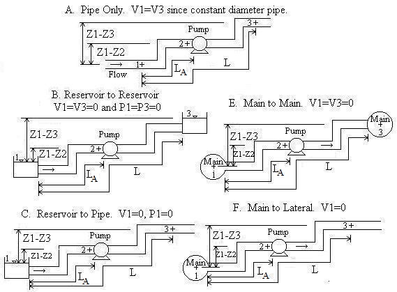
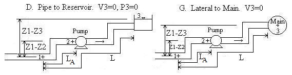
Piping Scenarios
Pipe A is the pipe upstream from the pump (i.e. the suction side pipe).
Convention for Z1-Z2 and Z1-Z3:
If location 1 is above location 2, then Z1-Z2 should be
entered as positive. If location 2 is above location 1, then Z1-Z2
should be entered as negative. Likewise for Z1-Z3.
Equations and Methodology Back to Calculation
Pump operating point calculator on this page uses the steady state energy equation. Minor losses (due to valves, pipe bends, etc.) and major losses (due to pipe friction) are included. The Hazen-Williams equation for friction losses is used. The equations are standard equations which can be found in most fluid mechanics textbooks (see References). A pump curve is included in the calculation. Determination of the pump curve requires that the user enter the two extreme points on the curve - head when capacity is zero, and capacity when head is zero. Then, a parabola with a negative curvature is fit through the two points. This parabola is used since it is a good approximation of a typical pump curve and does not require users to enter a multitude of data points. And, oftentimes, pump catalogs only give the two extreme points on the curve rather than a graph showing the complete curve.
Pump Curve
To provide an example of a pump curve developed using the equation H=Hmax[1-(Q/Qmax)2],
let Qmax=1500 gpm (when head is zero) and Hmax=900 ft (when Q is
zero). The pump curve used in the calculation will look like:
All of the calculations on this page have analytic (closed form) solutions except for "Solve for V, Q", "Q known. Solve for Diameter", and "V known. Solve for Diameter". These three calculations required a numerical solution. Our solution utilizes a modified implementation of Newton's method that finds roots of the equations with the result accurate to 8 significant digits. All of the calculations utilize double precision, but results are shown to eight significant figures. "V known. Solve for Diameter" may find two diameters which give the same velocity - if this is the case, both diameters are shown.
Variables Units: L=length, P=pressure, T=time
Back to Calculation
A = Pipe area [L2].
C = Hazen-Williams coefficient. See table
below.
D = Pipe inside diameter [L].
DH = Driving Head [L] = left side of the first equation
above. Also equals the right side of the equation which is the sum of major and minor losses.
g = Acceleration due to gravity = 32.174 ft/s2 = 9.8066 m/s2
hf = Major losses for entire pipe [L].
hfA = Major losses for pipe upstream of pump (pipe A) only [L].
hm = Minor losses for entire pipe [L].
hmA = Minor losses for pipe upstream of pump (pipe A) only [L].
H = Total dynamic head [L]. Also known as system head or head supplied by
pump.
Hmax = Maximum head that pump can provide [L]. It is the head
when Q=0.
k = Unit conversion factor = 1.318 for English units = 0.85 for Metric units.
K = Sum of minor loss coefficients for entire pipe. See table below for values.
KA = Sum of minor loss coefficients for pipe upstream of pump (pipe
A).
L = Total pipe length [L].
LA = Length of pipe upstream of pump (pipe A) [L].
NPSHA = Net positive suction head available [L].
Patm = Atmospheric (or barometric) pressure [P]. Standard
atmospheric pressure = 14.7 psi = 29.92 inch Hg = 760 mm Hg = 1 atm = 101,325 Pa = 1.01
bar. Note that your local atmospheric pressure is different from standard
atmospheric pressure.
Pv = Vapor pressure of fluid [P]. Expressed as an absolute
pressure. This value is built-in to the program as 2000 N/m2 (absolute)
for water at 15oC.
P1 = Gage pressure at location 1 of the system [P]. Location 1
could be the surface of a reservoir open to the atmosphere (thus P1=0),
or the pressure in a supply main (same as a tank under pressure), or location 1 could
simply be a location in a pipe upstream of the pump.
P1-P3 = Pressure difference between locations 1 and 3 [P].
Q = Flowrate [L3/T]. Also known as discharge or capacity.
Qmax = Maximum flowrate on pump curve [L3/T].
Corresponds to point on pump curve where head is zero.
S = Specific Weight of Water (i.e. weight density; weight per unit volume)
= 62.4 lb/ft3 for English units = 9800 N/m3 for Metric units
V1 = Velocity of fluid at location 1. This is determined when
you select a scenario. If location 1 is a reservoir or main (Scenarios B, C, E, and
F), then V1 is automatically set to 0 because the velocity head of the
fluid in the reservoir or main (or pressure tank) is much smaller than in the attached
pipeline. This is a standard assumption in fluid mechanics. However, if
location 1 is inside the suction side pipeline, then V1 is
automatically computed as Q/A.
V3 = Velocity of fluid at location 3. This is determined when
you select a scenario. If location 3 is a reservoir or main (Scenarios B, D, E, and
G), then V3 is automatically set to 0 because the velocity head of the
fluid in the reservoir or main (or pressure tank) is much smaller than in the attached
pipeline. This is a standard assumption in fluid mechanics. However, if
location 3 is inside your discharge side pipeline, then V3 is
automatically computed as Q/A.
Z1-Z2 = Elevation of location 1 minus elevation of pump
[L]. If the pump is above location 1, then enter this value as negative.
Z1-Z3 = Elevation of location 1 minus elevation of location
3 [L].
Common Questions
Back to Calculation
What is net positive suction head? It is the sum of the heads that push
fluid into the pump less the suction side losses. Most pumps have a minimum
requirement for NPSH, called NPSHR. If the NPSH
available by the piping system (NPSHA) is lower than NPSHR,
then the pump will not function properly and may overheat.
What is Driving Head? DH is the sum of heads supplied by the pump,
elevation, pressure, and velocity differences between the inlet and outlet system
boundaries. DH is equivalent to the sum of minor and major losses.
How is Total dynamic head different than Driving head? Total dynamic head, H,
is the head that the pump must provide to overcome major losses, minor losses, and
elevation, pressure, and velocity head differences between outlet and inlet. H
may be more or less than DH depending on whether the elevation, pressure, and/or
velocity head differences are beneficial or must be overcome.
Your program is great! What are its limitations? Pipes must all have
the same diameter. The fluid must be water. Our approximation for the pump
curve may not be close enough to your actual pump curve to give sufficiently accurate
results.
Do you have more common questions and answers somewhere else on your website?
Yes, see our Hazen-Williams calculation
without pump curves.
Where can I find additional information? References
Table of Hazen-Williams Coefficients
Back to Calculation
Compiled from References
| Material | C | Material | C |
| Asbestos Cement | 140 | Copper | 130-140 |
| Brass | 130-140 | Galvanized iron | 120 |
| Brick sewer | 100 | Glass | 140 |
| Cast-Iron: | Lead | 130-140 | |
| New, unlined | 130 | Plastic | 140-150 |
| 10 yr. old | 107-113 | Steel: | |
| 20 yr. old | 89-100 | Coal-tar enamel lined | 145-150 |
| 30 yr. old | 75-90 | New unlined | 140-150 |
| 40 yr. old | 64-83 | Riveted | 110 |
| Concrete/Concrete-lined: | |||
| Steel forms | 140 | Tin | 130 |
| Wooden forms | 120 | Vitrified clay (good condition) | 110-140 |
| Centrifugally spun | 135 | Wood stave (avg. condition) | 120 |
Table of Minor Loss Coefficients (K is unit-less)
Back to Calculation
Compiled from References
| Fitting | Km | Fitting | Km |
| Valves: | Elbows: | ||
| Globe, fully open | 10 | Regular 90°, flanged | 0.3 |
| Angle, fully open | 2 | Regular 90°, threaded | 1.5 |
| Gate, fully open | 0.15 | Long radius 90°, flanged | 0.2 |
| Gate 1/4 closed | 0.26 | Long radius 90°, threaded | 0.7 |
| Gate, 1/2 closed | 2.1 | Long radius 45°, threaded | 0.2 |
| Gate, 3/4 closed | 17 | Regular 45°, threaded | 0.4 |
| Swing check, forward flow | 2 | ||
| Swing check, backward flow | infinity | Tees: | |
| Line flow, flanged | 0.2 | ||
| 180° return bends: | Line flow, threaded | 0.9 | |
| Flanged | 0.2 | Branch flow, flanged | 1.0 |
| Threaded | 1.5 | Branch flow, threaded | 2.0 |
| Pipe Entrance (Reservoir to Pipe): | Pipe Exit (Pipe to Reservoir) | ||
| Square Connection | 0.5 | Square Connection | 1.0 |
| Rounded Connection | 0.2 | Rounded Connection | 1.0 |
| Re-entrant (pipe juts into tank) | 1.0 | Re-entrant (pipe juts into tank) | 1.0 |
Error Messages
Back to Calculation
Some or all values may be computed even with error messages, even though physically the situation cannot occur.
"An input is < 0." The following values must be entered as
≥ 0: K and KA. One or more of them was
entered as <0.
"An input is ≤ 0." The following values must be entered as
positive: Q, V, D, L, C, Qmax, Hmax, LA.
One or more of them was entered as ≤0.
"KA must be ≤ K." Minor loss coefficient for pipe
A cannot exceed the minor loss coefficient for the entire pipe system.
"LA must be ≤ L". The length of pipe A
cannot exceed the length of the entire pipe.
"P1+Patm must be >0." The sum of P1+Patm
gives P1 in absolute pressure. It is physically impossible to
have an absolute pressure ≤ 0 since that implies a complete vacuum at location
1.
"Need P1-(P1-P3)+Patm >0."
The absolute pressure at location 3 is less than 0 absolute. It is physically impossible to have a complete vacuum.
"Q must be ≤ Qmax." System flowrate cannot be
entered as greater than the maximum flow rate that the pump can deliver.
"Tanks open so P1-P3=0 for B." This message
occurs if Scenario B (reservoir to reservoir) is selected and Solve for P1-P3
is selected. Reservoirs are defined to be open to the atmosphere, so they have a
pressure difference of zero by default. If you have tanks that are under pressure,
select Scenario E (main to main) instead.
"Pump not needed. H will be ≤0." The system characteristics
that were entered result in a negative total dynamic head which means that a pump is not
necessary to deliver the flow. There are enough elevation, pressure, and/or velocity
head differences to overcome the major and minor losses without the need of a pump.
For this situation, it would be better to run our Hazen-Williams
calculation that doesn't incorporate a pump curve.
"Infeasible Input. DH will be ≤0." Driving head (the left
hand side of the first equation shown above in Equations) must be
positive in order for fluid to flow. The system and pump characteristics entered
result in DH being ≤ 0.
"Infeasible Input. (DH-hm)≤0." The difference (DH-hm)
is ≤ 0 implying that major losses will also be ≤0 which is impossible for a
flowing fluid.
"Infeasible Input (DH-hf )<0." The difference (DH-hf
) is < 0 implying that minor losses will also be <0, which is impossible.
"Infeasible input." Driving head and/or major losses are ≤0;
or minor losses are < 0.
© 1999-2026 LMNO Engineering, Research, and Software, Ltd. All rights reserved.
LMNO Engineering, Research, and Software, Ltd.
7860 Angel Ridge Rd. Athens, Ohio 45701 USA Phone: (740) 707‑2614
LMNO@LMNOeng.com
https://www.LMNOeng.com