Newsletters |
LMNO Engineering, Research, and Software, Ltd. |
Index to all Newsletters LMNO Engineering home page
email: LMNO@LMNOeng.com |
|
2019
February 13, 2019. Water Quality Volume - new calculator
2018
October 17, 2018. Hydraulic Jump in Circular Pipe - new calculator
August 22, 2018. Fire Hydrant Flow Test Analysis Calculator
June 19, 2018. Hydraulic Jump in Circular Pipe
2017
December 8, 2017. New Leak Rate Calculator
November 16, 2017. New Groundwater Calculators
September 29, 2017. New Riprap Rock Sizing Calculator
April 20, 2017. New Pressure Calculations and Stand-alone Calculations
March 14, 2017. Partially Full Inclined Cylinder Volume Calculation - now with table and graph
2016
October 20, 2016. Flume graphical and tabular calculator
August 18, 2016. Gradually Varied Flow graphical and tabular calculator
March 31, 2016. A Common Question
2015
July 19, 2015. Gas Viscosity Calculator
2014
September 8, 2014. Two Topics - mobile calculations and venturi flow meter
2013
July 22, 2013. Time to Empty a Tank
February 5, 2013. Water Velocity in a Tank at Various Heights above a Drain
LMNO Engineering, Research, and Software, Ltd.
The fluid flow calculations website: https://www.LMNOeng.com
7860 Angel Ridge Rd. Athens, Ohio 45701 USA (740) 707-2614
LMNO@LMNOeng.com
Newsletter. February 13, 2019.
New calculation - Water Quality Volume
https://www.LMNOeng.com/Hydrology/WaterQualityVolume.php
WQv = P A Rv
WQv = Water quality volume (volume units such as cubic meters, m3).
P = Precipitation (depth units such as meters).
A = Watershed area (area units such as square meters, m2).
Rv = Volumetric runoff coefficient (unit-less).
Rv is based on a watershed's imperviousness ratio i.
If a watershed has an area of 80,000 m2 and 20,000 m2 of the watershed is impervious surfaces such as buildings, parking lots, and roads, then:
i = 20,000 m2 / 80,000 m2 = 0.25 or 25%.
Since many localities use different polynomial equations for Rv, our calculator allows you to enter the coefficients. The calculator computes Rv and WQv. We also have two built-in commonly-used equations for Rv: the Driscoll equation and the Urbonas equation.
Please let me know if questions. Thank you for your interest in the LMNO Engineering newsletter,
Ken Edwards, Ph.D., P.E. (Owner/Engineer)
LMNO Engineering, Research, and Software, Ltd.
https://www.LMNOeng.com LMNO@LMNOeng.com
You received this free newsletter because you requested it at our website. If you no longer wish to receive it, send a message stating
"Discontinue Newsletter" to LMNO@LMNOeng.com.
© 2019 LMNO Engineering, Research, and Software, Ltd.
LMNO Engineering, Research, and Software, Ltd.
The fluid flow calculations website: https://www.LMNOeng.com
7860 Angel Ridge Rd. Athens, Ohio 45701 USA (740) 707-2614
LMNO@LMNOeng.com
Newsletter. October 17, 2018.
New calculator - Hydraulic Jump in Sloped Circular Pipe
https://www.LMNOeng.com/HydraulicJumpPipe/HydraulicJumpPipe.php
You may recall my newsletter of June 19 when I mentioned that I would be presenting at the 2018 National Hydraulic Engineering Conference in Columbus, Ohio, on August 29. The title of the presentation was "Computation of Hydraulic Jump's Sequent Depth in Sloped Circular Water Pipe."
We have now written software to compute the sequent depth in a downward sloped circular pipe (or culvert).
To my knowledge (as of when this newsletter is being written), there are no published reports of the sequent depth computation in a sloped circular pipe. However, there are equations and graphs available for sequent depth in a horizontal pipe (e.g. Lowe, 2008).
A hydraulic jump is an open channel flow phenomenon that occurs when fast (i.e. supercritical flow, Froude number, F, greater than 1) transitions to slow (i.e. subcritical flow F<1) often due to an obstruction or transition to a milder pipe slope. In a pipe, a hydraulic jump could cause the pipe to flow full resulting in additional pressure on the pipe walls and trapped air. Thus, if a hydraulic jump is anticipated in a pipeline design, it is helpful to know if the pipe will flow full or if it will remain unpressurized following the jump. Our calculation shows that if a horizontal pipe sequent depth method is used to predict the sequent depth in a sloped pipe, the sequent depth will be under-estimated. Thus, using a sloped pipe calculator for a sloped pipe is necessary.
Please let me know if questions. Thank you for your interest in the LMNO Engineering newsletter,
Ken Edwards, Ph.D., P.E. (Owner/Engineer)
LMNO Engineering, Research, and Software, Ltd.
https://www.LMNOeng.com LMNO@LMNOeng.com
Reference:
Lowe, N. J. (2008). Theoretical Determination of Subcritical Sequent Depths for Complete and Incomplete Hydraulic Jumps in Closed Conduits of Any Shape. Brigham Young University Scholars Archive. Master of Science thesis. Retrieved from
https://scholarsarchive.byu.edu/cgi/viewcontent.cgi?referer=https://www.google.com/&httpsredir=1&article=2618&context=etd
You received this free newsletter because you requested it at our website. If you no longer wish to receive it, send a message stating
"Discontinue Newsletter" to LMNO@LMNOeng.com.
© 2018 LMNO Engineering, Research, and Software, Ltd.
LMNO Engineering, Research, and Software, Ltd.
The fluid flow calculations website: https://www.LMNOeng.com
7860 Angel Ridge Rd. Athens, Ohio 45701 USA (740) 707-2614
LMNO@LMNOeng.com
Newsletter. August 22, 2018.
Fire Hydrant Flow Test Analysis Calculator
https://www.LMNOeng.com/Hydrant/hydrant.php
Our newest calculator is for fire hydrant flow test analysis. A municipal fire hydrant test typically utilizes two fire hydrants - a flowing hydrant and a pressure hydrant. Before the hydrant flow test, static pressure is measured at the pressure hydrant. Then the flow hydrant is opened and the flow rate measured after flow becomes relatively steady. At this time, the residual pressure is measured at the pressure hydrant.
In the United States, a standard equation using static pressure, residual pressure, and flow rate is used to predict the flow rate if the pressure hydrant measured 20 psi residual. The equation simulates a situation where a fire hose with a pump is connected to the flowing hydrant which draws the pressure down in the residual hydrant. The value of 20 psi is the common residual pressure reference value for predicting flow rate.
The equation and calculator can be found at https://www.LMNOeng.com/Hydrant/hydrant.php
Please let me know if questions. Thank you for your interest in the LMNO Engineering newsletter,
Ken Edwards, Ph.D., P.E. (Owner/Engineer)
LMNO Engineering, Research, and Software, Ltd.
https://www.LMNOeng.com LMNO@LMNOeng.com
You received this free newsletter because you requested it at our website. If you no longer wish to receive it, send a message stating
"Discontinue Newsletter" to LMNO@LMNOeng.com.
© 2018 LMNO Engineering, Research, and Software, Ltd.
LMNO Engineering, Research, and Software, Ltd.
The fluid flow calculations website: https://www.LMNOeng.com
7860 Angel Ridge Rd. Athens, Ohio 45701 USA (740) 707-2614
LMNO@LMNOeng.com
Newsletter. June 19, 2018.
Hydraulic Jump in Circular Pipe
I will be making a presentation titled, "Computation of Hydraulic Jump's Sequent Depth in Sloped Circular Water Pipe," co-authored by Debbie Edwards and Steve McKenzie, at the 2018 National Hydraulic Engineering Conference in Columbus, Ohio, on August 29.
A hydraulic jump occurs in an open channel (or partially full closed conduit) when there is a transition from supercritical flow to subcritical flow. At the conference, I will present our methodology for determining the depth after the jump (a.k.a. sequent depth or conjugate depth) in a sloping circular pipe. A review of methods for computing sequent depth in horizontal conduits.
Why would you be interested in computing the sequent depth in a sloped circular pipe? If water or other liquid is being conveyed in a pipe from a high elevation to a lower elevation where the topography varies from steep to mild and you do not want the pipe to flow full anywhere in the system, there will likely be a hydraulic jump. Computing the sequent depth is necessary so that the selected pipe diameters are large enough to accommodate the sequent depth.
While we do not yet have a website calculation for hydraulic jump in a circular pipe, we have a calculation for a hydraulic jump in a horizontal rectangular channel.
Please let me know if questions. Thank you for your interest in the LMNO Engineering newsletter,
Ken Edwards, Ph.D., P.E. (Owner/Engineer)
LMNO Engineering, Research, and Software, Ltd.
https://www.LMNOeng.com LMNO@LMNOeng.com
You received this free newsletter because you requested it at our website. If you no longer wish to receive it, send a message stating
"Discontinue Newsletter" to LMNO@LMNOeng.com.
© 2018 LMNO Engineering, Research, and Software, Ltd.
LMNO Engineering, Research, and Software, Ltd.
The fluid flow calculations website: https://www.LMNOeng.com
7860 Angel Ridge Rd. Athens, Ohio 45701 USA (740) 707-2614
LMNO@LMNOeng.com
Newsletter. December 8, 2017.
Liquid Leak Rate Calculator
https://www.LMNOeng.com/Flow/LeakRate.php
Our newest calculator computes leak rate of a liquid from a pipe, tube, or tank. The leak rate is based on the pressure difference between the inside and outside of the pipe, the crack or hole area, and specific gravity of the liquid.
Our pipe leak rate calculator computes the leak rate of a liquid out of a circular or non-circular crack or hole in a pipe or tank. The leak rate calculation has built-in specific gravity values for water, seawater, diesel fuel, SAE 30 oil, and gasoline. Specific gravity can be entered for other liquids. If the leak rate is known, the calculator can compute pressure or crack area (and diameter).
The leak rate web page shows the equation used to compute leak rate, and its derivation based on the Bernoulli equation. Please let me know if you have any questions. Thank you for your interest in the LMNO Engineering newsletter,
Ken Edwards, Ph.D., P.E. (Owner/Engineer)
LMNO Engineering, Research, and Software, Ltd.
https://www.LMNOeng.com LMNO@LMNOeng.com
You received this free newsletter because you requested it at our website. If you no longer wish to receive it, send a message stating
"Discontinue Newsletter" to LMNO@LMNOeng.com.
© 2017 LMNO Engineering, Research, and Software, Ltd.
LMNO Engineering, Research, and Software, Ltd.
The fluid flow calculations website: https://www.LMNOeng.com
7860 Angel Ridge Rd. Athens, Ohio 45701 USA (740) 707-2614
LMNO@LMNOeng.com
Newsletter. November 16, 2017.
Unsteady Groundwater Flow Calculator:
https://www.LMNOeng.com/Groundwater/theis.php
Groundwater Transmissivity Calculator:
https://www.LMNOeng.com/Groundwater/transmissivity.php (free)
We loaded two new groundwater calculators in October. The first one listed above computes unsteady groundwater flow to a pumping or injection well in a confined aquifer using the Theis equation. The Theis equation was named for the researcher who presented the solution method in 1935. The equation predicts the amount of groundwater drawdown in a confined aquifer at a specified time since commencement of pumping and distance from the pumped well. The equation also requires knowledge of the aquifer's transmissivity and storage coefficient, which are aquifer properties.
The second calculation listed above computes aquifer transmissivity based on an aquifer's hydraulic conductivity and thickness. Hydraulic conductivity can be determined experimentally or, for a given formation type (sandy, gravelly, etc.), can be obtained from tables.
The groundwater drawdown in an aquifer is useful for groundwater remediation pump-and-treat systems. Knowing aquifer drawdown is also helpful for water supply systems that rely on groundwater pumping.
Please let me know if you have any questions. Thank you for your interest in the LMNO Engineering newsletter,
Ken Edwards, Ph.D., P.E. (Owner/Engineer)
LMNO Engineering, Research, and Software, Ltd.
https://www.LMNOeng.com LMNO@LMNOeng.com
You received this free newsletter because you requested it at our website. If you no longer wish to receive it, send a message stating
"Discontinue Newsletter" to LMNO@LMNOeng.com.
© 2017 LMNO Engineering, Research, and Software, Ltd.
LMNO Engineering, Research, and Software, Ltd.
The fluid flow calculations website: https://www.LMNOeng.com
7860 Angel Ridge Rd. Athens, Ohio 45701 USA (740) 707-2614
LMNO@LMNOeng.com
Newsletter. September 29, 2017.
New Riprap Rock Sizing Calculator
https://www.LMNOeng.com/Channels/riprap.php
We loaded our new riprap sizing calculator on September 23. The calculator uses the Isbash equation to size rocks (or stones) for river and stream channel stabilization. In the calculator, you enter the water velocity. The software computes the minimum rock size that will not get transported away. You also type in the rock specific gravity and an Isbash constant of 0.86 or 1.2. A constant of 0.86 should be used to determine the rock size to keep loose surface rocks from moving due to the water current. A constant of 1.2 can be used if the rock is in a pile with other rocks allowing them more resistance due to the group of rocks. Using an Isbash constant of 1.2 results in smaller rock size than using a value of 0.86.
The calculation can alternatively be solved for water velocity. In this case, you would enter the rock size.
Please let me know if you have any questions. Thank you for your interest in the LMNO Engineering newsletter,
Ken Edwards, Ph.D., P.E. (Owner/Engineer)
LMNO Engineering, Research, and Software, Ltd.
https://www.LMNOeng.com LMNO@LMNOeng.com
You received this free newsletter because you requested it at our website. If you no longer wish to receive it, send a message stating
"Discontinue Newsletter" to LMNO@LMNOeng.com.
© 2017 LMNO Engineering, Research, and Software, Ltd.
LMNO Engineering, Research, and Software, Ltd.
The fluid flow calculations website: https://www.LMNOeng.com
7860 Angel Ridge Rd. Athens, Ohio 45701 USA (740) 707-2614
LMNO@LMNOeng.com
Newsletter. April 20, 2017
New Pressure Calculations and Stand-alone Calculations
We used to sell stand-alone calculations (programs that don't require an internet connection) for $150 (US Dollars). All of our calculations were Java applets. However, most browsers stopped supporting Java applets.
.We recently finished converting all of the Java applets on our website to PHP programs, which run on all computers and browsers. Since PHP programs require an internet connection, we stopped selling stand-alones - until now.
We now offer stand-alone calculations as compiled PHP programs (.exe file extension). A free downloadable example ( additionStandalone.exe ) is provided at https://www.LMNOeng.com/register.php. Stand-alone programs cost $150 (US Dollars) each and contain all of the information that you see on a particular web page including the calculator, text, and equations. Our stand-alone calculations do not require an internet connection and have no expiration date.
We also have three new free on-line calculators:
https://www.LMNOeng.com/Pressure/DischargeCoefficient.php
https://www.LMNOeng.com/Pressure/PressureDrop.php
https://www.LMNOeng.com/Pressure/PressureLoss.php
"Discharge Coefficient" converts an orifice discharge coefficient to a pipe flow minor loss coefficient. "Pressure Drop" computes pressure drop in a horizontal pipe for incompressible laminar flow. "Pressure Loss" computes pressure drop in a horizontal pipe for incompressible flow with Reynolds number between 4000 and 100,000. These are simple calculators. If you need more complex calculations, please see our full list of calculators at https://www.LMNOeng.com.
Please let me know if you have any questions. Thank you for your interest in the LMNO Engineering newsletter,
Ken Edwards, Ph.D., P.E. (Owner/Engineer)
LMNO Engineering, Research, and Software, Ltd.
https://www.LMNOeng.com LMNO@LMNOeng.com
You received this free newsletter because you requested it at our website. If you no longer wish to receive it, send a message stating
"Discontinue Newsletter" to LMNO@LMNOeng.com.
© 2017 LMNO Engineering, Research, and Software, Ltd.
LMNO Engineering, Research, and Software, Ltd.
The fluid flow calculations website: https://www.LMNOeng.com
7860 Angel Ridge Rd. Athens, Ohio 45701 USA (740) 707-2614
LMNO@LMNOeng.com
Newsletter. March 14, 2017
Partially Full Inclined Cylinder Volume Calculation - now with graph and table https://www.LMNOeng.com/Volume/InclinedCyl.php
The newest feature on our website is that our partially full inclined cylinder volume calculator now provides graphical and tabular results. It will produce a rating curve of volume versus measured distance.
The calculation is helpful for partially full inclined tanks or partially full pipes installed on an incline. The user enters the cylinder diameter, length, and angle from horizontal.
The calculation allows you to enter the liquid depth measurement several ways:
1. Vertical distance (i.e. perpendicular to liquid surface) from bottom of tank to liquid surface (i.e. wet depth).
2. Vertical distance from top of tank down to liquid surface (i.e. dry depth).
3. Distance from bottom of tank to liquid surface measured perpendicular to bottom of tank (i.e. parallel to the end caps).
4. Distance from top of tank to liquid surface measured perpendicular to top of tank.
Since the cylinder is at an angle, the user must also indicate how far from the downhill edge of the tank the distance measurement is made.
In addition to entering the type of measurement, the user also enters the distance interval for the table and units for the distances and volume. Charts and tables are produced by clicking on the "Click to Calculate" button and then clicking on the "Graph (opens in new tab)" or "Table (opens in new tab)" links.
A full description of the governing equations, inputs, and outputs are shown on the web page. If you are interested in the mass of liquid in the tank, just multiply the output volume by the liquid density.
The calculation has a demonstration mode for an angle of 15 degrees and tank diameter of 2 meters.
Please let me know if you have any questions. Thank you for your interest in the LMNO Engineering newsletter,
Ken Edwards, Ph.D., P.E. (Owner/Engineer)
LMNO Engineering, Research, and Software, Ltd.
https://www.LMNOeng.com LMNO@LMNOeng.com
You received this free newsletter because you requested it at our website. If you no longer wish to receive it, send a message stating
"Discontinue Newsletter" to LMNO@LMNOeng.com.
© 2017 LMNO Engineering, Research, and Software, Ltd.
LMNO Engineering, Research, and Software, Ltd.
The fluid flow calculations website: https://www.LMNOeng.com
7860 Angel Ridge Rd. Athens, Ohio 45701 USA (740) 707-2614
LMNO@LMNOeng.com
Newsletter. October 20, 2016
Flume Calculator for Water Flow Rate Measurement
Now with graph and table. Now mobile-device-friendly.
https://www.LMNOeng.com/Flumes/flumes.php
We recently loaded a new version of our flume calculator. It shows flume rating curves (flow rate versus head) in graphical and tabular form. The calculation has a demonstration mode, so you can see how it functions. The calculation includes four types of flumes - trapezoidal, U, Parshall, and rectangular. It can be found at https://www.LMNOeng.com/Flumes/flumes.php
.After clicking on "Click to Calculate," links for the graph and table will appear. Clicking on the links will bring up the graph and table in new tabs. The tabular output is comma-separated, so you can copy/paste the values into a spreadsheet to make custom graphs.
Flumes are open channel flow measurement devices. They are installed in natural and man made narrow to wide waterways. Flumes are designed so that there is a control section, also known as a critical flow section. The water profile changes from subcritical (low velocity) to critical to supercritical (high velocity) in the control section. The design allows a single measurement of water depth (head) in order to determine the discharge. Our flume calculations are based on equations published by the International Organization for Standardization (ISO).
Please let me know if you have any questions. Thank you for your interest in the LMNO Engineering newsletter,
Ken Edwards, Ph.D., P.E. (Owner/Engineer)
LMNO Engineering, Research, and Software, Ltd.
https://www.LMNOeng.com LMNO@LMNOeng.com
You received this free newsletter because you requested it at our website. If you no longer wish to receive it, send a message stating
"Discontinue Newsletter" to LMNO@LMNOeng.com.
© 2016 LMNO Engineering, Research, and Software, Ltd.
LMNO Engineering, Research, and Software, Ltd.
The fluid flow calculations website: https://www.LMNOeng.com
7860 Angel Ridge Rd. Athens, Ohio 45701 USA (740) 707-2614
LMNO@LMNOeng.com
Newsletter. August 18, 2016
Gradually Varied Flow (GVF) Calculator
Now with graph and table. Now mobile-device-friendly.
https://www.LMNOeng.com/Channels/gvf.php
On August 4, we loaded our newest mobile-friendly calculation. It is for gradually varied flow (GVF, which is also known as backwater flow). It is at https://www.LMNOeng.com/Channels/gvf.php. The calculation has a nice demonstration mode, so you can see graphs and tables showing water depth upstream or downstream of a barrier. In addition to water depth, it will also plot and give a table for velocity, Froude number, and top width versus distance in the demonstration mode. In addition to the graph and table, numbers for depth, velocity, Froude number, and other parameters are output at any distance specified by the user.
After clicking on "Click to Calculate", links for the graph and table will appear. Clicking on the links will bring up the graph and table in new tabs. The tabular output is comma-separated, so you can copy/paste the values into a spreadsheet to make custom graphs.
As background, GVF and RVF (rapidly varied flow) are terms used to classify open channel flows - such as flow in rivers, canals, and culverts. RVF occurs over short distances such as when water flows over a weir or dam, drops off the end of a pipe, or encounters an hydraulic jump. GVF occurs over long distances such as water approaching a weir, dam, or drop-off; or following a sluice gate.
In long prismatic (constant cross-section geometry) channels, the water will attempt to reach the "normal depth" (also known as "uniform flow depth"). Normal depth is the water depth determined using Manning's equation (or Chezy's equation). How the water depth changes with distance as it approaches normal depth is called a GVF profile. A GVF profile is obtained through a computation of water depth versus distance along the channel length. A GVF computation typically involves starting at a known depth (e.g. at a dam) and making successive computations upstream using the continuity equation and energy slope in Manning's equation (rather than using the channel bottom slope). It is a numerical computation. Thus for highest accuracy, it is desirable to use small distance increments as our program does. If you have had a course in open channel flow, you might recall the different GVF profile types - such as M1, M2, M3, S1, S2, S3, etc.
Please let me know if you have any questions. Thank you for your interest in the LMNO Engineering newsletter,
Ken Edwards, Ph.D., P.E. (Owner/Engineer)
LMNO Engineering, Research, and Software, Ltd.
https://www.LMNOeng.com LMNO@LMNOeng.com
You received this free newsletter because you requested it at our website. If you no longer wish to receive it, send a message stating
"Discontinue Newsletter" to LMNO@LMNOeng.com.
© 2016 LMNO Engineering, Research, and Software, Ltd.
LMNO Engineering, Research, and Software, Ltd.
The fluid flow calculations website: https://www.LMNOeng.com
7860 Angel Ridge Rd. Athens, OH 45701 USA (740) 707-2614
LMNO@LMNOeng.com
Newsletter. March 31, 2016
A Common Question
The most common question I am asked is, "I know the pressure in my pipe. What is the flow rate?" That question is not simple to answer. Unless the fluid is passing through a control section, such as a choked flow section, then two pressure readings are needed. If flow is discharging downstream to the atmosphere, then you have a second known pressure (atmospheric pressure) and flow can be determined.
Alternatively, if more information is provided about the piping system, then the additional information may be sufficient to calculate the flow rate. For instance, if there is a tank upstream or downstream of the pressure reading, then the pressure in the tank can be used as the second data point and flow can be computed.
Our Liquid or Gas Pipe Design calculator (https://www.LMNOeng.com/DarcyWeisbach.php) demonstrates how elevation change, pressure change, and/or pumping can drive the flow of a liquid or gas. In the calculation, you can enter pipe diameter, length, loss coefficients for fittings, pressure change, and elevation change, and the calculation will compute the pipe flow rate. Alternatively, you can enter flow rate, and the calculation will compute the other parameters.
Please let me know if you have any questions. Thank you for your interest in the LMNO Engineering newsletter,
Ken Edwards, Ph.D., P.E. (Owner/Engineer)
LMNO Engineering, Research, and Software, Ltd.
https://www.LMNOeng.com LMNO@LMNOeng.com
You received this free newsletter because you requested it at our website. If you no longer wish to receive it, send a message stating "Discontinue Newsletter" to LMNO@LMNOeng.com.
© 2016 LMNO Engineering, Research, and Software, Ltd.
LMNO Engineering, Research, and Software, Ltd.
The fluid flow calculations website: https://www.LMNOeng.com
7860 Angel Ridge Rd. Athens, OH 45701 USA (740) 707-2614
LMNO@LMNOeng.com
Newsletter. July 19, 2015
Gas Viscosity Calculator
https://www.LMNOeng.com/Flow/GasViscosity.php
Our most popular calculator is our free gas viscosity calculator. Gas viscosity is used to compute pressure drop when gases flow through pipes. Our calculator computes gas viscosity as a function of temperature for air, natural gas, hydrocarbon vapor, ammonia, carbon dioxide, carbon monoxide, hydrogen, nitrogen, and sulfur dioxide. Dynamic viscosity is primarily a function of temperature, rather than pressure, for pressures up to 500 psi (34.5 bar) (Crane, 1988).
Our gas viscosity calculator is based on the methodology in Crane (1988) and the CRC Handbook of Chemistry and Physics (1984). The viscosity of many gases can be computed by the Sutherland formula shown on the web page. For natural gases with various specific gravities, the Sutherland formula does not apply. In this case, we have taken data points from graphs in very small intervals and input them into our calculation. Then, the calculation interpolates linearly between the points.
In addition to selecting the gas of interest, the calculation allows you to choose the temperature units of Celsius, Kelvin, Fahrenheit, or Rankine and the dynamic viscosity units of lb-s/ft2, N-s/m2, poise, and centipoise. Note that 1 poise = 0.1 N-s/m2 and 1 centipoise = 0.001 N-s/m2 (per https://www.LMNOeng.com/units.php).
Please see our full list of 80 calculations for pressure pipe flow, choked gas flow, water hammer, open channel flow, hydrology, groundwater, drag force, and tank sizing at https://www.LMNOeng.com.
Please let me know if you have any questions. Thank you for your interest in the LMNO Engineering newsletter,
Ken Edwards, Ph.D., P.E. (Owner/Engineer)
LMNO Engineering, Research, and Software, Ltd.
https://www.LMNOeng.com LMNO@LMNOeng.com
References:
Chemical Rubber Company (CRC). 1984. CRC Handbook of Chemistry and Physics. Weast, Robert C., editor. 65th edition. CRC
Press, Inc. Boca Raton, Florida. USA.
Crane Company. 1988. Flow of fluids through valves, fittings, and pipe. Technical Paper No. 410 (TP 410).
You received this free newsletter because you requested it at our website. If you no longer wish to receive it, send a message stating "Discontinue Newsletter" to LMNO@LMNOeng.com.
© 2015 LMNO Engineering, Research, and Software, Ltd.
LMNO Engineering, Research, and Software, Ltd.
The fluid flow calculations website: https://www.LMNOeng.com
7860 Angel Ridge Rd. Athens, Ohio 45701 USA (740) 707-2614
LMNO@LMNOeng.com
Newsletter. September 8, 2014
Two Topics:
Mobile-Device-Friendly Calculations
Venturi Flow Meter Calculation: https://www.LMNOeng.com/venturi.php
My last newsletter was on July 22, 2013. We are in the process of converting our software from the Java language to the PHP language. Having our programs in PHP will enable them to be viewable on mobile devices. They will also more readily run on computers since you will not need to download any additional software from the web. Currently, you need to download the Java Runtime Environment to run our Java applets. We have converted 29 programs so far. Please see our home page https://www.LMNOeng.com for a list of programs (the PHP programs have a + next to them).
The most recent program that we converted to PHP is our venturi flow meter calculator. A venturi flow meter is a differential pressure flow meter. Differential pressure is the difference in pressure between a high pressure upstream tap and a low pressure tap at the throat of the venturi. Knowing the differential pressure, upstream diameter, throat diameter, and fluid density and viscosity, the flow rate can be computed.
Standards have been written by various professional organizations (e.g. International Organization of Standards and American Society of Mechanical Engineers) so that a venturi flow meter manufactured to conform to the standard can be used "out of the box" without any calibration. Venturi flow meters have the advantage over nozzle and orifice meters (also differential pressure flow meters) because venturi meters result in a lower overall pressure loss through the device. Our venturi flow meter calculation allows you to enter a variety of units and solve for flow rate, differential pressure, or throat diameter.
Thank you for your interest in the LMNO Engineering newsletter,
Ken Edwards, Ph.D., P.E. (Owner/Engineer)
You received this free newsletter because you requested it at our website. If you no longer wish to receive it, send a message stating "Discontinue Newsletter" to LMNO@LMNOeng.com.
© 2014 LMNO Engineering, Research, and Software, Ltd.
LMNO Engineering, Research, and Software, Ltd.
The fluid flow calculations website: https://www.LMNOeng.com
7860 Angel Ridge Rd. Athens, Ohio 45701 USA (740) 707-2614
LMNO@LMNOeng.com
Newsletter. July 22, 2013
Time to Empty a Tank
https://www.LMNOeng.com/Tank/TankTime.htm
We are sometimes asked how long it will take to empty a tank or drain a pond. Our
calculation to compute the time for the liquid level in a tank to drop can be found at https://www.LMNOeng.com/Tank/TankTime.htm
. The calculation uses the equation:
t = A/(a C) (Hi0.5 - Hf0.5) (2/g)0.5
where (sample units are shown in parentheses):
a = Orifice area (m2).
A = Tank cross-sectional area (looking down on the tank, m2).
C = Orifice discharge coefficient.
g = Acceleration due to gravity (9.8066 m/s2).
Hi = Initial liquid depth above orifice centerline (m).
Hf = Final liquid depth above orifice centerline (m).
t = Time for liquid to drop from Hi to Hf (sec).
For instance, if C=0.6, Orifice diameter=0.01 m, Tank diameter=0.5 m, Hi=3 m, Hf=0.2
m, then:
a = π d2 /4 = pi (0.01m)2 /4 = 7.854e-5 m2
A = π D2 /4 = pi (0.5m)2 /4 = 0.1963 m2
t = (0.1963 m2) / [(7.854e-5 m2)(0.6)] [(3
m)0.5 - (0.2 m)0.5] (2/9.8066 m/s2)0.5
= 2417 sec = 40.3 minutes
In addition to time, the calculation can compute one of the other variables - orifice
coefficient, initial depth, final depth, tank area (or diameter), or orifice area (or
diameter). Our calculation allows you to select a variety of units.
Thank you for your interest in the LMNO Engineering newsletter,
Ken Edwards, Ph.D., P.E. (Owner/Engineer/Programmer)
You received this free newsletter because you requested it at our website. If you no
longer wish to receive it, send a message stating "Discontinue Newsletter" to LMNO@LMNOeng.com.
© 2013 LMNO Engineering, Research, and Software, Ltd
LMNO Engineering, Research, and Software, Ltd.
The fluid flow calculations website: https://www.LMNOeng.com
7860 Angel Ridge Rd. Athens, OH 45701 USA (740) 707-2614
LMNO@LMNOeng.com
Newsletter. February 5, 2013
Water Velocity in a Tank at Various Heights above a Drain
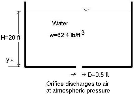
Consider a tank (or swimming pool) where there is a drain (orifice) on the flat bottom of the tank which discharges freely to atmospheric pressure as shown in the figure. If the diameter of the opening is D=0.5 ft and the water depth remains constant at H=20 ft, then what are the pressure and velocity of the flowing water at various heights y directly above the orifice?
The orifice discharge velocity Vo is: Vo = (2gH)0.5 = [(2)(32.2 ft/s2)(20 ft)]0.5 = 35.89 ft/s where g = acceleration due to gravity = 32.2 ft/s2
The orifice area Ao is: Ao = π D2 / 4 = π (0.5 ft)2 / 4 = 0.1963 ft2 where π = 3.14159....
The flow rate Q out of the orifice is: Q = C Ao Vo = (0.6)(0.1963 ft2)(35.89 ft/s) = 4.228 ft3/s where C is the orifice discharge coefficient, typically 0.6 but depends on its rounded-ness.
The approximate streamline paths are shown in the following figure.
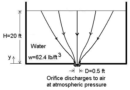
Think of the streamlines in three dimensions, sort of like a funnel. To determine the velocity at heights y directly above the orifice, we need to determine an area distribution. An approximation is to use the surface area of a hemisphere. The surface area of a sphere is 4 π r2 where r is the sphere radius. The surface area of a hemisphere is then 2 π r2. Thus, the area distribution as a function of height y is: A(y) = 2 π y2
Then the velocity V(y) at heights above the orifice is (from conservation of mass for a constant density fluid like water): V(y) = Q / A(y)
The pressure P(y) at heights y above the orifice is computed from the Bernoulli equation: P(y) = w { [Vo2 - V(y)2] / (2g) - y} where w = weight density of water = 62.4 lb/ft3
A sample calculation at y = 2 ft:
A(y=2 ft) = 2 π y2 = 2 π (2 ft)2 = 25.13 ft2
V(y=2 ft) = Q / A(y) = (4.228 ft3/s) / (25.13 ft2) = 0.1682 ft/s
P(y=2 ft) = w { [Vo2 - V(y)2] / (2g) - y}= (62.4 lb/ft3) { [(35.89 ft/s)2 - (0.1682 ft/s)2] / [(2)(32.2 ft/s2)] - 2 ft } = 1123 lb/ft2 = 7.800 lb/in2 = 7.800 psi
A table can be developed:
| y | V(y) | P(y) |
| (ft) | (ft/s) | (psi) |
| 0.5 | 2.69 | 8.40 |
| 1 | 0.673 | 8.23 |
| 2 | 0.168 | 7.80 |
| 5 | 0.0269 | 6.50 |
| 10 | 0.00673 | 4.33 |
| 15 | 0.00299 | 2.17 |
| 20 | 0.00168 | 0 |
As y increases, velocity decreases and pressure approaches hydrostatic pressure, w(H-y) in lb/ft2 or w(H-y)/144 in psi.
Thank you for your interest in the LMNO Engineering newsletter and the fluid flow
calculations website https://www.LMNOeng.com,
Ken Edwards, Ph.D., P.E. (Owner/Engineer/Programmer)
You received this free newsletter because you requested it at our website. If you no
longer wish to receive it, send a message stating "Discontinue Newsletter" to LMNO@LMNOeng.com.
© 2013 LMNO Engineering, Research, and Software, Ltd.
© 2013-2024 LMNO Engineering, Research, and Software, Ltd. (All Rights Reserved)
LMNO Engineering, Research, and Software, Ltd.
7860 Angel Ridge Rd. Athens, Ohio USA +1(740) 707-2614
LMNO@LMNOeng.com https://www.LMNOeng.com