
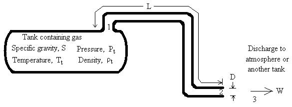
Flow Diagram.
Gas flows from the tank, into the pipe, and discharges.
Units: atm=atmosphere, cm=centimeter, cP=centiPoise, ft=foot, g=gram, hr=hour, k=kilo (1000), kPa=kiloPascal, kg=kilogram, km=kilometer, lb=pound, m=meter, min=minute, mm=millimeter, M=Mega (million, 106) or Thousand (103) depending on context, MM=Million, MPa=MegaPascal, Mscfh=thousand std cubic foot per hour, MMscfd=million std cubic foot per day, mol=mole, N=Newton, N/m2=Newton per square meter (same as Pascal), Normal=std conditions, Pa=Pascal, s=second, psf=pound per square foot (lb/ft2), psi=pound per square inch, psia=psi (absolute), psig=psi (gage), scfd=standard cubic foot per day, scfh=standard cubic foot per hour, scfm=standard cubic foot per minute.
Pressure Information: Standard conditions are 15 oC (i.e. 288.15 K, 59 oF, 518.67 oR) and 1 atm (i.e. 101,325 N/m2, 14.696 psia). If gage pressure units are selected, the calculation assumes atmospheric pressure is 1 atm. The program uses 1 atm to convert between gage and absolute pressures.
Introduction
Choked flow calculator computes the mass flow rate through a pipe based on tank pressure and temperature, pipe length and diameter, minor losses, discharge pressure, and gas properties. Temperatures, pressures, densities, velocities, and Mach numbers are computed at all transition points (in the tank, at the pipe entrance, in the pipe at the exit, and in the surroundings at the discharge). As the gas flows through the pipe, the pressure drops. Hence, density drops and velocity increases. If choking occurs, it will only occur at the pipe exit (Munson et al., 1998) for flow through a constant diameter pipe.
In the choked flow calculator, gas flowing steadily from a tank into a pipe and discharging to the atmosphere (or another tank) is modeled using Fanno flow. Fanno flow assumes that the pipe is adiabatic. Adiabatic means that there is no heat transfer into or out of the pipe. This is physically accomplished by insulating the pipe. Even if the pipe is not insulated, the adiabatic assumption is probably more realistic than an isothermal assumption for short lengths of pipe. In longer pipelines that are isothermal (constant temperature) and subsonic, the Weymouth calculation may be more suitable for computing flow rates and pressure drops.
Equations
For a gas flowing steadily from a tank to a pipe under Fanno flow conditions (adiabatic), the procedure follows that of Fanno flow in Gerhart et al. (1992) and Munson et al. (1998). An example in Perry (1984) uses figures which represent Fanno flow for choked flow. The following equations are solved simultaneously to compute mass flow rate, temperatures, pressures, velocities, and Mach numbers.
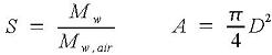
Gas specific gravity and pipe cross-sectional area:
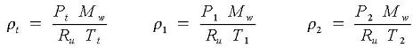
Gas densities using ideal gas law:
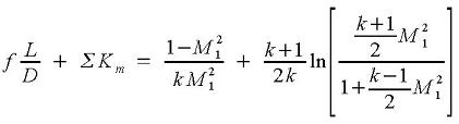
The choked flow calculator checks to see if choked flow occurs. If flow is choked, then choking occurs at location 2. Choked flow occurs if P3<P2*. P2* is the static pressure at location 2 if flow is choked. If choked flow occurs, then the * is dropped from the superscripts at location 2 for simplicity. ΣKm represents losses due to elbows and the pipe entrance. M1 is computed from:
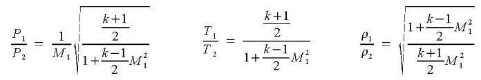
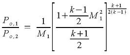
Conditions are stagnant in the tank. Assuming the tank exit behaves isentropically:
Pt = Po,1 Tt = To,1 ρt = ρo,1 and:

Since choked flow occurs at location 2, M2=1.0 and:
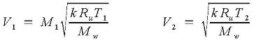
Velocities are:
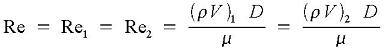
Since pipe diameter and mass flow rate are constant along the pipe, the Reynolds number is the same at locations 1 and 2:
Moody friction factor is computed from the following equations:
If laminar flow (Re < 4000 and any ε/D), then
![]()
If turbulent flow (4000 < Re < 108 and ε/D < 0.05), then Colebrook equation (Munson et al., 1998, p. 494):
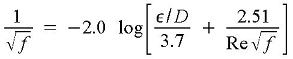
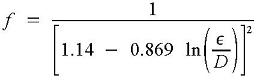
If fully turbulent flow (Re > 108 and 0 < ε/D < 0.05), then Streeter et al. (1998, p. 289):
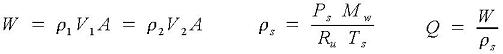
Mass flow rate, density at standard conditions, and flow rate at standard conditions are:
Variables
The units shown for the variables are SI (International System of Units); however, the equations above are valid for any consistent set of units. Our calculation allows a variety of units; all unit conversions are accomplished internally.
A = Pipeline cross-sectional area, m2.
D = Pipe inside diameter, m.
f = Moody friction factor. (Note that Moody friction factor is 4 times the Fanning
friction factor. Fanning friction factor is often used by chemical engineers.)
k = Gas specific heat ratio. Specific heat at constant pressure divided by specific heat
at constant volume, Cp/Cv. Default values at 15oC or 20oC
from Munson et al. (1998). k actually varies with temperature and can range from, using
methane as an example, 1.32 at 50oF to 1.28 at 250oF (GPSA, 1998, p.
13-6).
Km = Minor loss coefficient for pipe entrance, bends, etc. Since flow is choked
(if the calculation proceeds), do not include an exit loss coefficient.
ln = Natural logarithm (base e, where e=2.71828...).
log = Common logarithm (base 10).
L = Pipe length, m.
M = Mach number.
Mw = Molecular weight of gas, kg/mole.
P = Absolute pressure, N/m2 absolute.
Q = Flow rate at standard conditions, Normal m3/s.
Re = Reynolds number.
Ru = Universal gas constant, 8.3144126 N-m/mol-K (CRC, 1983, p. F-208).
S = Specific gravity of gas, relative to air (Sair=1).
T = Absolute temperature, Kelvin.
V = Velocity, m/s.
W = Mass flow rate, kg/s.
ε = Pipe roughness, m. Default values from Munson et al. (1998).
μ = Gas dynamic viscosity, kg/m-s. The program assumes this is constant even though
temperature (thus viscosity) varies along the pipe.
π = 3.14159....
ρ = Gas density, kg/m3.
Σ = Summation.
Subscripts:
t = Tank.
1 = Pipe entrance.
2 = Pipe exit.
3 = Surroundings.
o = Stagnation property.
s = std = Standard (or "Normal") conditions. The word "standard" is
used for English units. The term "Normal" is used with SI units, as in Nm3/s
which means "Normal m3/s". Standard and Normal conditions for our
choked flow calculation are 15 oC (i.e. 288.15 K, 59 oF,
518.67 oR) and 1 atm (i.e. 101,325 N/m2, 14.696 psia) from
Perry (1984, p. 3-167). Some industries use different temperature and pressure for standard (or Normal)
conditions. To convert the mass flow rate computed by our choked flow calculation to
volumetric flow at a different Ts and Ps, use our gas flow conversions page.
If gage pressure units are selected, the calculation assumes atmospheric pressure is Ps. The program uses Ps to convert between gage and absolute pressures.
Minor Loss Coefficients (Km)
From Munson et al. (1998).
| Fitting | Km | Fitting | Km |
| Pipe Entrance (Tank to Pipe): | Elbows: | ||
| Square Connection | 0.5 | Regular 90o, flanged | 0.3 |
| Rounded Connection | 0.2 | Regular 90o, threaded | 1.5 |
| Long radius 90o, flanged | 0.2 | ||
| Long radius 90o, threaded | 0.7 | ||
| 180o return bends: | Long radius 45o, threaded | 0.2 | |
| Flanged | 0.2 | Regular 45o, threaded | 0.4 |
| Threaded | 1.5 |
Error Messages
Input checks:
"Need S > 1e-8", "Need Viscosity > 1e-20 N-s/m2", "Need k > 1.0000001", "Need D > 1e-9 m", "Need Pipe Roughness > 0", "Need Tt > 1e-8 Kelvin", "Need Pt > 1e-8 N/m2 absolute", "Need P3 > 1e-8 N/m2 absolute", "Need Pt > P3", "Need Km + f L / D ≥ 1e-8", "Need L > 0". Specific gravity, viscosity, specific heat ratio, pipe diameter, surface roughness, tank temperature, tank pressure, discharge pressure, pipe length must be acceptable values.Pipe length can be 0.0 since the software can model an orifice without actually having a pipe.
Run-time messages:
"Flow is choked". This message will appear during normal running of the program if flow is choked."Flow is subsonic". If the conditions are such (e.g. low Pt, high P3, high L, high Km, low D), then flow will not be choked and the calculation will stop.
"Mach at 1 not found". The program is unable to compute the Mach number at the pipe inlet.
"Re or ε/D out of range". Reynolds number or roughness-to-diameter ratio is out of range.
"Moody f not found". The program is unable to determine the friction factor. Reynolds number or roughness-to-diameter ratio may be out of range.
References
Chemical Rubber Company (CRC). 1983. CRC Handbook of Chemistry and Physics. Weast, Robert C., editor. 63rd edition. CRC Press, Inc. Boca Raton, Florida.
Gerhart, P. M., R. J. Gross, and J. I. Hochstein. 1992. Fundamentals of Fluid Mechanics. Addison-Wesley Pub. Co. 2ed.
Gas Processors Suppliers Association (GPSA). 1998. Engineering Data Book (fps [foot-pound-second] version). Gas Processors Association. 11ed.
Perry, R. H. and D. W. Green, editors. 1984. Perry's Chemical Engineers' Handbook. McGraw-Hill, Inc. 6ed.
Munson, B.R., D. F. Young, and T. H. Okiishi. 1998. Fundamentals of Fluid Mechanics. John Wiley and Sons, Inc. 3ed.
Streeter, V. L., E. B. Wylie, and K. W. Bedford. 1998. Fluid Mechanics. McGraw-Hill. 9ed.
© 2010-2026 LMNO Engineering, Research, and Software, Ltd. All rights reserved.
LMNO Engineering, Research, and Software, Ltd.
7860 Angel Ridge Rd. Athens, Ohio 45701 USA Phone: (740) 707‑2614
LMNO@LMNOeng.com
https://www.LMNOeng.com