
Units: cm=centimeter, ft=foot, gal=U.S. gallon, hr=hour, m=meter, MGD=million gallons (US) per day, min=minute, s=second
Topics: Equations Comparison of ASTM D1941 and ISO 9826 Variables Error Messages References
Introduction
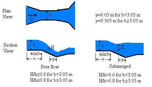
Our Parshall flume calculator is based on the ISO 9826 (1992) standard. The standard is valid for submerged as well as free-flowing Parshall flumes. A free flowing flume can be identified by the drop in water depth at the flume throat. In submerged flow, the downstream water backs up into the throat swallowing the drop making the drop difficult or impossible to identify. Analysis of submerged flow requires two head measurements - one in the approach channel and one in the throat. Free flow requires only the upstream head measurement.
Parshall flumes must be built with their dimensions in strict accordance with specifications in published documents such as the ISO 9826 and ASTM D1941 (1991) standards or USBR (1997). Flumes (like weirs) are designed to force a transition from sub-critical to super-critical flow. In the case of Parshall flumes, the transition is caused by designing flumes to have a narrowing at the throat and a drop in the channel bottom. Such a transition causes flow to pass through critical depth in the flume throat. At the critical depth, energy is minimized and there is a direct relationship between water depth and velocity (and flowrate). However, it is physically very difficult to measure critical depth in a flume because its exact location is difficult to determine and may vary with flowrate. Through mass conservation, the upstream depth is related to the critical depth. Therefore, discharge can be determined by measuring the upstream depth, which is a highly reliable measurement.
Equations and Methodology
The methodology for our Parshall flume calculation follows that of ISO 9826 (1992). ASTM D 1941 (1991) also addresses Parshall flumes but has pages of tabular data which are more difficult to implement into a computer program compared to the figures and equations of ISO 9826.
Validity
The LMNO Engineering calculation allows 0≤h≤3 m
and 0.01<b<16m, but the
calculation is most accurate when used within the ISO 9826 recommendations of
h≤2 m and 0.152 ≤ b ≤ 15.24 m.
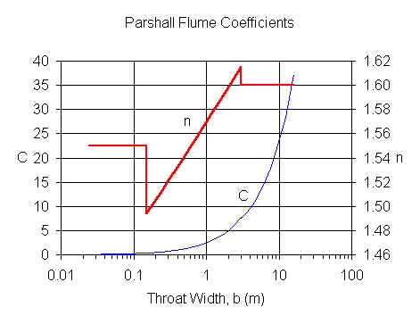
For b≤0.152 m, C and n values are from Herschy (1995).
For b>0.152 m, C and n values are from ISO 9826 (1992),
equations 10 and 11.
Free flow
Free flow occurs when a hydraulic jump is visible at the throat; that is, when the downstream head is significantly less than the upstream head. Our calculation defines free flow as occurring when H/h≤0.6 for b<3.05 m or when H/h≤0.8 for b≥3.05 m. These criteria (called "modular limits") are similar, but not identical, to the ISO 9826 criteria.
For free flow,
Q = C hn where Q is in m3/s and h is in m
Submerged flow
Submerged flow occurs when a hydraulic jump is not visible at the throat; that is, when the downstream head is sufficiently high that it "drowns out" or "swallows up" the hydraulic jump. In our calculation, submerged flow occurs when H/h>0.6 for b<3.05 m and when H/h>0.8 for b≥3.05 m.
For submerged flow, ISO equation 12 is re-written as:
Q = C hn - Qe where C and n are found from the
above figure based on width (b). Qe accounts for the effects of
submergence.
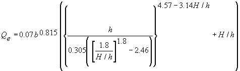
For b<3.05 m, ISO 9826 equation 13 provides the following equation for Qe which is implemented in our calculation:
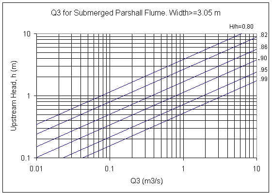
For b≥3.05 m, Qe=CsQ3, where
Cs = 0.3281*b.
ISO 9826 Figure 2 is a graph of Q3 as a
function of H/h and h. LMNO Engineering fit equations to all of the lines in
the ISO figure for use in our calculation. A graph using our equations for selected
H/h ratios is shown:
Comparison of ISO and ASTM Methods
Back to Calculation
Both ISO 9826 and ASTM D1941 present methods for computing discharge through Parshall flumes. Since a Parshall flume is a standard flume, the two methods should be similar. Looking at the two standards, they at first appear somewhat different because ISO 9826 is in SI units while ASTM D1941 uses predominantly English units. Further, the ISO standard presents information in tables, equations, and figures while ASTM D1941 uses tables almost exclusively. Curious as to how well the two methods compare, we developed the following table. We also have done other comparisons but, due to space considerations, have chosen not to show the results on this web page. In general, there is good agreement for free flow, but in some cases the submerged flow rates are significantly different, such as for the b=0.152 m case shown below.
| Width, b | Upstream Head, h | Flow Regime | ASTM Flow, Q | ISO Flow, Q |
|---|---|---|---|---|
| 0.152 m (6 inch) |
0.24 m (0.7874 ft) |
Free Flow | 0.0400 m3/s(1) | 0.0408 m3/s(2) |
| Submerged, H/h=0.84 | 0.0309 m3/s(3) | 0.0237 m3/s(4) | ||
| 7.62 m (25 ft) |
0.6096 m (2.0 ft) |
Free Flow | 8.13 m3/s(1) | 8.13 m3/s(2) |
| Submerged, H/h=0.9 | 7.34 m3/s(5) | 7.36 m3/s(6) | ||
|
(1) based on Table 2 in ASTM D1941. (2) based on Equation 10 in ISO 9826. (3) based on Tables 2 and 6B in ASTM D1941. (4) based on Equations 10, 12, and 13 in ISO 9826. (5) based on Tables 2, 9A, and 9C in ASTM D1941. (6) based on Equations 11, 12, and 14 and Figure 2 in ISO 9826. |
||||
Variables
Back to Calculation
ISO 9826 specifies the indicated units for the equations shown above. Our
calculation allows you to select a variety of units from dropdown menus.
m=meters, s=seconds
b = Throat width [m].
C = Parshall flume constant [empirical units].
Cs = Submergence coefficient [unit-less]. This is not the submergence
ratio.
h = Measured upstream head [m].
H = Measured downstream head [m]. Only needed if the flume is submerged, or to
determine mathematically if the flume is submerged. Usually, one can visually see if
there is a hydraulic jump, but determining the ratio H/h is a quantitative method.
H/h = Submergence ratio. Flume is submerged if H/h>0.6 for
b<3.05m or if H/h>0.8
for b≥3.05 m.
n = Parshall flume power constant [unit-less].
Q = Flow rate (discharge) through flume [m3/s].
Qe = Reduction in flow rate due to submergence [m3/s].
Q3 = Flow factor for determining Qe if b≥3.05 m [m3/s].
Error Messages
Back to Calculation
"Need h ≥ 0". Negative head was entered. If h=0,
calculation automatically sets Q=0.
"Need h ≤ 3 m". Head cannot exceed 3 m.
"Need H > 0". For submerged flow, downstream head must be
positive.
"Need H/h > 0", "Need H/h ≤ 1". If
submerged flow is selected, H/h must be in this range.
"Need b > 0". Throat width must be positive.
"Need 0.01≤b≤16 m". Flume throat width must be in this
range.
"Qe will be > Chn ". Message will only appear if submerged flow.
Input values result in negative Q.
Usually this occurs with very small upstream heads h and when H/h>0.6
resulting in Qe > Chn.
See variables and equations for Qe, C, and n.
Input checks for graph.
If one of these messages
appears, the graph will not proceed. Note that if any value is out of range in the
upper portion of the calculation, a graph will not be shown.
"Min h must be ≥0", "Min H/h must be ≥0".
Minimum head or H/h ratio entered for graph cannot be < 0.
"Max h must be ≤ 3 m". Graph has maximum limit of h=3 m.
"Need 0.6<Max H/h≤1". Message will only appear if b<3.05 m. Q is independent of H/h until H/h becomes greater than 0.6. So to avoid a "boring" graph showing a constant value for Q, the calculation requires that max H/h be in the range where submergence affects Q.
"Need 0.8<Max H/h≤1". Message will only appear if b≥3.05 m. Q is independent of H/h until H/h becomes greater than 0.8. So to avoid a "boring" graph showing a constant value for Q, the calculation requires that max H/h be in the range where submergence affects Q.
"Min/Max must be ≤ 0.99". Minimum value entered for graph must be less than 0.99 times maximum value entered for graph. Otherwise, the minimum and maximum are too close together to have good axis labels for the graph.
"Min must be < Max". Minimum value entered for graph must be less than maximum value entered for graph.
Run-time errors.
The following messages may be generated by the graphing portion of the calculation:
"No graph for input range". The entire range from minimum to maximum
results in parameters that are out of the range of validity of the flume equations.
Usually this occurs for submerged flow with very small upstream heads h
and when H/h>0.6 resulting in
Qe > Chn.
See variables and equations for Qe, C, and n.
"Q=0 when low h and/or high H/h". Some heads in the range entered for the graph result in parameters that are invalid, so those could not be computed and were plotted at Q=0. Message appears on graph and table pages.
Graph Comments
When the graph "Q vs. H/h (h constant)" is selected, you may notice a discontinuity in the graph at H/h=0.6 for b<3.05 m or H/h=0.8 for b≥3.05 m. The discontinuity occurs because the flow is transitioning from free flow to submerged flow. For some ranges of H/h, you may observe something similar to the following:
Graph of Q vs. H/h, for b=0.5 m and h=0.5 m
The discharge for H/h<0.6 does not appear to be shown. However, our software scales the y-axis based on the maximum value on the curve. In this case, the maximum value on the curve is 0.398 m3/s which blends in with the boxed outline of the graph. The flow is 0.398 m3/s for all H/h <0.6.
References
Back to Calculation
American Society for Testing and Materials (ASTM D1941-91). 1991. Standard test method for open channel flow measurement of water with the Parshall flume. Available at http://www.astm.org.
Herschy, Reginald W. 1995. Streamflow Measurement. E & FN Spon (an imprint of Chapman and Hall). 2ed.
International Organization of Standards (ISO 9826). 1992. Measurement of liquid flow in open channels - Parshall and SANIIRI flumes. Reference number: ISO 9826:1992(E). ISO documents can be downloaded as .PDF files for a fee at http://webstore.ansi.org.
USBR. 1997. U.S. Department of the Interior, Bureau of Reclamation. Water Measurement Manual. 1997. 3ed. Available from https://www.usbr.gov/tsc/techreferences/mands/wmm/index.htm .
© 2001-2025 LMNO Engineering, Research, and Software, Ltd. All rights reserved.
LMNO Engineering, Research, and Software, Ltd.
7860 Angel Ridge Rd. Athens, Ohio 45701 USA Phone: (740) 707-2614
LMNO@LMNOeng.com
https://www.LMNOeng.com