
Units: cm=centimeter, ft=foot, g=gram, gal=U.S. gallon, in=inch, kg=kilogram, lb=pound, m=meter, mbar=millibar,
min=minute, mm=millimeter, N=Newton, s=second.
Bernoulli Equation
Topics: Introduction Applications Variables Error Messages References
Introduction
The Bernoulli equation is named in honor of Daniel Bernoulli (1700-1782). Many phenomena regarding the flow of liquids and gases can be analyzed by simply using the Bernoulli equation. However, due to its simplicity, the Bernoulli equation may not provide an accurate enough answer for many situations, but it is a good place to start. It can certainly provide a first estimate of parameter values. Modifications to the Bernoulli equation to incorporate viscous losses, compressibility, and unsteady behavior can be found in other (more complex) calculations on this website and in the links shown at the right. When viscous effects are incorporated, the resulting equation is called the "energy equation".
The Bernoulli equation assumes that your fluid and device meet four criteria:
1. Fluid is incompressible, 2. Fluid is inviscid, 3. Flow is steady, 4.
Flow is along a streamline.
The Bernoulli equation is used to analyze fluid flow along a streamline from a location 1 to a location 2. Most liquids meet the incompressible assumption and many gases can even be treated as incompressible if their density varies only slightly from 1 to 2. The steady flow requirement is usually not too hard to achieve for situations typically analyzed by the Bernoulli equation. Steady flow means that the flowrate (i.e. discharge) does not vary with time. The inviscid fluid requirement implies that the fluid has no viscosity. All fluids have viscosity; however, viscous effects are minimized if travel distances are small.
To aid in applying the Bernoulli equation to your situation, we have included many
built-in applications of the Bernoulli equation. They are described below. For
additional information about the Bernoulli equation and applications, please see the references at the bottom of this page.
Applications
To calculator
Pitot Tube

A pitot tube is used to measure velocity based on a differential pressure measurement. The Bernoulli equation models the physical situation very well. In the Bernoulli equation, Z2=Z1 and V2=0 for a pitot tube. A pitot tube can also give an estimate of the flowrate through a pipe or duct if the pitot tube is located where the average velocity occurs (average velocity times pipe area gives flowrate). Oftentimes, pitot tubes are negligently installed in the center of a pipe. This would give the velocity at the center of the pipe, which is usually the maximum velocity in the pipe, and could be twice the average velocity.
Dam (or weir)
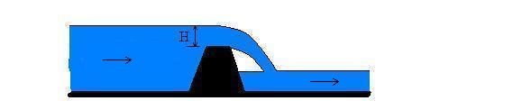
Using the Bernoulli equation to determine flowrate over a dam assumes that the velocity upstream of the dam is negligible (V1=0) and that the nappe is exposed to atmospheric pressure above and below. Experiments have shown that the Bernoulli equation alone does not adequately predict the flow, so empirical constants have been determined which allow better agreement between equations and real flows. To obtain better accuracy than the Bernoulli equation alone provides, use our weir calculations (Rectangular weir, V-notch weir, Cipoletti weir).
Sluice gate
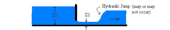
A sluice gate is often used to regulate open channel flows, and the Bernoulli equation
does an adequate job of modeling the situation. A hydraulic jump may or may not
occur downstream of a sluice gate. Be sure that Z2 is not measured downstream of a hydraulic jump.
The Bernoulli equation cannot be used
across hydraulic jumps since energy is dissipated. Usually for sluice gates Z1>>Z2,
so the Bernoulli equation can be simplified to Q = Z2 W (2 g Z1)1/2
(Munson et al., 1998) - which is the equation used in our calculation.
Circular hole in tank (or pipe connected to tank)
Non-circular hole in tank (or duct, i.e. non-circular conduit, connected to tank)
Diagrams showing some situations which can be modeled with these two selections:
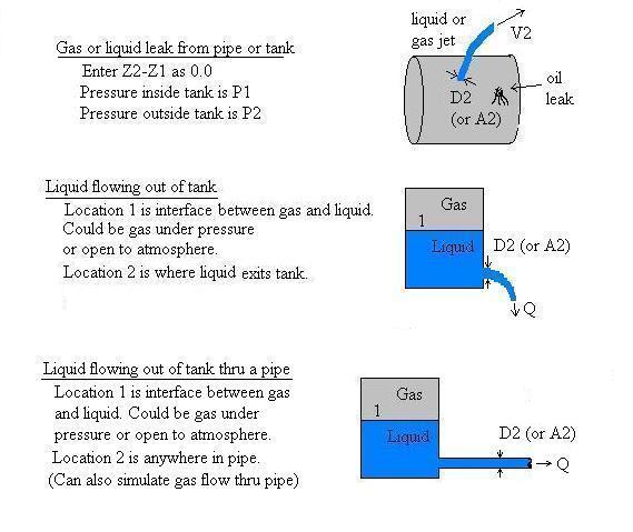
The Bernoulli equation does not account for viscous effects of the holes in tanks or
friction due to flow along pipes, thus the flowrate predicted by our Bernoulli equation
calculator will be larger than the actual flow. V1 is automatically set
to 0.0 - implying that location 1 is a device that has a large flow area so that the
velocity at location 1 (e.g. in a tank) is negligible compared to the velocity of fluid
leaving the tank. For comprehensive calculations which include viscous effects, try
the following calculations: Discharge from a tank, Circular liquid or gas pipes using Darcy-Weisbach losses, Circular water pipes using Hazen-Williams losses.
Circular pipe diameter change, Non-circular duct area change
Venturi flow meter (C=0.98), Nozzle flow meter (C=0.96),andOrifice
flow meter (C=0.6)

This selection is useful for determining the change in static pressure in a pipe due to a diameter change, determining flowrate, or designing a flow meter. Locations 1 and 2 should be as close together as possible; otherwise, viscous effects due to pipe friction will impact the pressure. However, flow meters normally have specified locations for the pressure taps.
If you select "Solve for D, W, or A", the diameter and/or or area at location 2 (D2 and/or A2) will be computed. For all but the flow meters, if you instead need to compute the diameter (or area) at location 1 (D1, A1), you can "fool" the calculation by reversing the signs on your pressure and elevation differences and enter the diameter (area) at location 2 as D1 (or A1). Then, the D2 (or A2) computed will actually be at location 1. You cannot do this for the flow meters since they require that D1 is greater than D2.
The venturi flowmeter analysis is based on the Bernoulli equation except for an empirical coefficient of discharge, C. V2 in the equation at the top of this page is known as the theoretical throat velocity. In our calculation, the velocity that is output for V2 is the actual throat velocity, CV2. Flowrate is computed as Q=CV2A2 (Munson et al. 1998) and A2=πD22/4. For simplicity, our Bernoulli venturi calculation uses a fixed value of C=0.98. However, it is well known that C is not fixed at 0.98 but varies as a function of Reynolds number and the material from which the meter is constructed. Also, most relationships for C are only valid for certain ranges of D1, D2 and D2/D1. For a more rigorous and accurate venturi calculation (yet one that has limits on some of the variables), please visit our comprehensive venturi flowmeter calculation.
For nozzle and orifice flow meters, Z2-Z1 is fixed at 0.0 since
these meters are typically installed in horizontal pipes (or the elevation difference
between locations 1 and 2 is negligible). Nozzle and orifice meters tend to have a
greater impact on the flow (greater energy loss) than venturi meters reflected by
generally lower C values. The C value is incorporated into the Bernoulli equation as
described above in the above paragraph for venturi meters. The C values of 0.96 and
0.6 are typical values that can be used for nozzles and orifices but will produce
substantial error for certain Reynolds numbers and geometries since C actually is a
function of pressure tap locations, Reynolds number, diameter ratio, and pipe diameter.
For more rigorous and accurate equations and computations (yet ones that have
limits on some of the variables), use our comprehensive nozzle and orifice calculations (liquid flow through nozzle, liquid flow
through orifice, gas flow through orifice).
Variables
[ ] indicates dimensions. [F]=Force, [L]=Length, [M]=Mass, [T]=Time, [F]=[M][L]/[T]. Subscripts: 1 indicates upstream location, 2 indicates downstream location.
To calculator
A = Cross-sectional area (i.e. area normal to flow direction) [L2].
font-style: normal;
If pipe is circular, then A=πD2/4
D = Diameter [L]. For flow meters, D2 is the flow meter's throat
diameter.
g = Acceleration due to gravity = 9.8066 m/s2 = 32.174 ft/s2.
The calculation converts all input variables to SI, performs computations, then converts
output variables to specified units.
H = Water depth above top of dam [L].
P = Pressure [F/L2].
Q = Flowrate (i.e. discharge) [L3/T].
W = Channel width [L].
Z = Elevation [L].
ρ = Mass density of fluid (Greek letter
"rho") [M/L3]. Densities built-into the calculation are at
standard atmospheric pressure which is 1 atmosphere (atm). Note that 1 atm=101,325
N/m2=1.01325 bar=760 mm Hg (0 oC)=2116 lb/ft2=14.7 psi=30.01 inch Hg
(60 oF)=29.92 inch Hg (32 oF).
Error Messages
To calculator
Messages are shown if you solve for a variable that is not used for the application. For example, you cannot solve for pressure difference across a sluice gate since the pressure difference is, by default, 0.0 since both the upstream and downstream water surfaces are exposed to atmospheric pressure.
Messages are also shown if a variable is entered as negative when it must be positive,
such as a diameter. Additionally, a message will be shown if entered values result
in a physically infeasible (impossible) situation - such as flow moving upward in a
contracting pipe and you entered a positive value for the pressure difference, P2-P1.
The pressure difference would have to be negative in order to have upward flow in a
contracting pipe (it may need to be quite a bit negative if Z2-Z1 is
large).
References
To calculator
Cited
Munson, B. R., D. F. Young, and T. H. Okiishi. 1998. Fundamentals of Fluid
Mechanics. John Wiley and Sons, Inc. 3ed.
Useful Resources
Gerhart, P. M, R. J. Gross, and J. I. Hochstein. 1992. Fundamentals of Fluid
Mechanics. Addison-Wesley Publishing Co. 2ed.
Potter, M. C. and D. C. Wiggert. 1991. Mechanics of Fluids. Prentice-Hall, Inc.
Roberson, J. A. and C. T. Crowe. 1990. Engineering Fluid Mechanics. Houghton Mifflin Co.
Streeter, V. L., E. B. Wylie, and K. W. Bedford. 1998. Fluid Mechanics. WCB/McGraw-Hill. 8ed.
White, F. M. 1979. Fluid Mechanics. McGraw-Hill, Inc.
© 2000-2026 LMNO Engineering, Research, and Software, Ltd. All rights reserved.
LMNO Engineering, Research, and Software, Ltd.
7860 Angel Ridge Rd. Athens, Ohio 45701 USA Phone: (740) 707-2614
LMNO@LMNOeng.com
https://www.LMNOeng.com