
Units: bbls=barrels, C=degrees Celsius, cm=centimeter, cP=centipoise, cSt=centistoke, F=degrees Fahrenheit, cfs=cubic feet per second, ft=feet, g=gram, gpm=US gallons per minute, gph=US gallons per hour, gpd=US gallons per day, hr=hour, in=inch, kg=kilogram, lb=pound, m=meters, min=minute, mm=millimeter, N=Newton, Pa=Pascal, psi=pound per square inch, s=second
Types of Pressure Taps for Small Bore Orifices
Introduction
Orifice flow meters are used to determine a liquid or gas flow rate by measuring the
differential pressure (P1 - P2) across the orifice plate. The
two standard pressure tapping arrangements for small bore orifices are shown in the
drawings; the location of the pressure taps affects the discharge coefficient
somewhat. Flange pressure taps penetrate the flange and are at a standard distance
of 1 inch (2.54 cm) from either side of the orifice. For corner taps, tappings are
right up against the orifice.
The LMNO Engineering small diameter orifice calculation is valid for orifices installed in pipes having pipe diameters between 1 cm and 5 cm (2 inch), and pipe Reynolds numbers greater than 1000. For larger diameter pipes, please see our Large Diameter Orifice Calculation for Liquids. We also have orifice calculations for gas flow (D<5 cm and D≥ 5 cm); and calculations for flow through nozzle and venturi flow meters.
Equations for Small Bore Orifice Plate for Liquids
Equations from ASME (2001)
Varible Definitions
[L]=Length units, [F]=Force units, [M]=Mass units, [T]=Time units.
A = Area [L2], C = Discharge Coefficient, d = Throat Diameter [L], D = Pipe Diameter [L],
h = Head Loss [L],
k = Equivalent Roughness of Pipe Material [L],
Km = Minor Loss Coefficient,
Δp = Differential Pressure [F/L2], Qm = Mass Flow Rate [M/T], Qv = Volumetric Flow Rate [L3/T], Red = Reynolds Number based on d, ReD = Reynolds Number based on D, V = Velocity [L/T],
w = Pressure Loss [F/L2],
ρ = Density [M/L3], ν = Kinematic Viscosity [L2/T].
w is the static pressure loss occurring from a distance of approximately D upstream of the orifice to a distance of approximately 6D downstream of the orifice. It is not the same as differential pressure. Differential pressure is measured at the exact locations specified in ASME (2001) (shown in the above figures). Km is computed to allow you to design pipe systems with orifices and incorporate their overall pressure loss, w.
Discharge Coefficients
From ASME (2001)
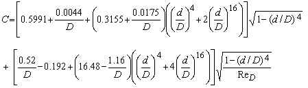
Flange Taps:
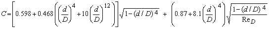
where D is in inches; and d/D and ReD are dimensionless. C is dimensionless.
Applicability:
Pipe Diameter, D
LMNO Engineering calculation requires 1 cm < D < 5.1 cm for both corner and flange
taps.
ASME (2001) suggests 1.2 cm ≤ D ≤ 4 cm for corner taps and 2.5 ≤ D ≤ 4 cm
for flange taps.
Diameter ratio, d/D
LMNO Engineering and ASME (2001) require 0.1 ≤ d/D ≤ 0.8 for corner taps and 0.15
≤ d/D ≤ 0.7 for flange taps.
Reynolds number based on pipe diameter, ReD
LMNO Engineering and ASME (2001) require ReD > 1000.
Error Messages
Messages indicating input values are out of the acceptable ranges:
"Need 1≤Density≤1e9 kg/m3", "Need
1e-19≤Viscosity≤1e9 m2/s", "Need 0.01≤D≤0.051 m",
"Need 1e-30≤Qv≤1e30 m3/s", "Need 1e-30≤Qm≤1e30
kg/s", "Need 1e-99≤Δp≤1e99 Pa", "Need ReD >
1000".
"Need 0.1≤d/D≤0.8" for corner taps. "Need
0.15≤d/D≤0.7" for flange taps.
Run-time messages. Computations not completed:
"ReD will be <1000". If solving for flow
rate. Unable to compute Q's. Value for Q will cause ReD to be <
1000 (out of range of validity).
"Δp too large". If solving for flow rate. Unable to
compute Q's because the differential pressure that you entered will cause the throat
velocity to exceed 1000 m/s, a velocity for which the calculation is not valid. The
calculation is not valid for supersonic flows.
"d/D will be too small" or "d/D will be too large".
If solving for d. Unable to compute d; value for d will cause d/D to be out
of range of validity.
Note
If your pipe diameter, D, is 2 inch (5.1 cm) or greater, use our Large Diameter Orifice
Calculation for Liquids based on ISO 5167. Or, try the simpler orifice calculation
on our Bernoulli page if your parameters are out of
range. The Bernoulli calculation is not as accurate, but won't give "parameter
out of range" error messages.
References
American Society of Mechanical Engineers (ASME). 2001. Measurement of fluid
flow using small bore precision orifice meters. ASME MFC-14M-2001.
International Organization of Standards (ISO 5167-1). 1991. Measurement of fluid flow by means of pressure differential devices, Part 1: Orifice plates, nozzles, and Venturi tubes inserted in circular cross-section conduits running full. Reference number: ISO 5167-1:1991(E).
International Organization of Standards (ISO 5167-1) Amendment 1. 1998. Measurement of fluid flow by means of pressure differential devices, Part 1: Orifice plates, nozzles, and Venturi tubes inserted in circular cross-section conduits running full. Reference number: ISO 5167-1:1991/Amd.1:1998(E).
© 2002-2026 LMNO Engineering, Research, and Software, Ltd. All rights reserved.
LMNO Engineering, Research, and Software, Ltd.
7860 Angel Ridge Rd. Athens, Ohio 45701 USA Phone: (740) 707‑2614
LMNO@LMNOeng.com
https://www.LMNOeng.com